15. Open Rails Cabs
OR supports both MSTS-compatible 2D cabs as well as native 3D cabs, even on the same locomotive.
For a full list of parameters, see Developing OR Content - Parameters and Tokens
15.1. 2D Cabs
OR supports with a high degree of compatibility all functions available in MSTS for 2D cabs, and provides some significant enhancements described in the next paragraphs.
15.1.1. ETCS circular speed gauge
A circular speed gauge accordingly to the standard European Train Control System (ETCS) can be added to the cabview. The information displayed in the Driver Machine Interface (DMI) is controlled via the TCS script. For more details, see C# engine scripting - Train Control System.
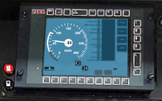
The gauge is added by the insertion of a block like the following into the .cvf file:
Digital (
    Type ( SPEEDOMETER DIGITAL )
    Style ( NEEDLE )
    Position ( 160 255 56 56 )
    ScaleRange ( 0 250 )
    Units ( KM_PER_HOUR )
)
It is also possible to display the full ETCS display using the following block instead:
ScreenDisplay (
    Type ( ORTS_ETCS SCREEN_DISPLAY )
    Graphic ( statictexture.ace ) Comment( 3D cab only, mandatory there )
    Position ( 280 272 320 240 )  Comment( 2D cab only )
    Units ( KM_PER_HOUR )
    Parameters (
        Mode FullSize
        MaxSpeed 180
        DisplayUnits 0
    )
)
The following commonly used MaxSpeed or ScaleRange values can be set
* 140, 150, 180, 240, 250, 260, 280, 400 for KM_PER_HOUR unit
* 87, 111, 155, 248 for MILES_PER_HOUR unit
The default value is 400 with KM_PER_HOUR unit.
The following DMI size variants are available:
FullSize displays the whole DMI,
SpeedArea displays only the left part with information about distance and speed,
PlanningArea displays only the right side planning area and navigation buttons.
The default value is FullSize
Use the MaxVisibleSpeed to set the highest speed displayed as a number,
if literal numbering is undesirable above this number on the circular speed gauge.
The default value is the MaxSpeed rounded to the highest tens below.
Use the DisplayUnits parameter to suppress diplaying the speed unit at the
bottom of the circular speed gauge. The default is 1, displaying the units.
Use the Graphic parameter in 3D cabs to designate the static texture inside
the .s file that will be replaced at runtime with the dynamic picture of the
display. This parameter is mandatory. If omitted, or the named texture cannot
be found in the model, no display will be shown.
15.1.2. Battery
The battery subsystem controls the low voltage power supply of the locomotive.
The following controls are available for the cabview:
ORTS_BATTERY_SWITCH_COMMAND_SWITCHcan be used if the battery switch is directly controlled from the cabORTS_BATTERY_SWITCH_COMMAND_BUTTON_CLOSEandORTS_BATTERY_SWITCH_COMMAND_BUTTON_OPENcan be used if the switch is controlled with two pushbuttons (one to close the switch and the other to open it)ORTS_BATTERY_SWITCH_ONcan be used to control a light on the cab showing the state of the battery switchORTS_BATTERY_VOLTAGEmonitors the battery voltage
Other controls can be disabled if the low voltage power supply is not available using the following parameter:
TwoState (
   Type ( ORTS_CIRCUIT_BREAKER_CLOSED TWO_STATE )
   ...
   DisabledIfLowVoltagePowerSupplyOff ( 1 )
)
By default, the cabview control will be completely hidden. You can also set a specific value for the control when it is disabled:
TwoState (
   Type ( SPEEDOMETER DIAL )
   ...
   DisabledIfLowVoltagePowerSupplyOff ( 1 )
   HideIfDisabled ( 0 )
   ValueIfDisabled ( 0 )
)
15.1.3. Master key
The master key controls the power supply of the cab.
The following controls are available for the cabview:
ORTS_MASTER_KEYcan be used in order to control the master keyORTS_CURRENT_CAB_IN_USEcan be used to indicate that the current cab is activeORTS_OTHER_CAB_IN_USEcan be used to indicate that another cab of the train is active
Other controls can be disabled if the cab power supply is not available using the following parameter:
TwoState (
   Type ( ORTS_CIRCUIT_BREAKER_CLOSED TWO_STATE )
   ...
   DisabledIfCabPowerSupplyOff ( 1 )
)
By default, the cabview control will be completely hidden. You can also set a specific value for the control when it is disabled:
TwoState (
   Type ( SPEEDOMETER DIAL )
   ...
   DisabledIfCabPowerSupplyOff ( 1 )
   HideIfDisabled ( 0 )
   ValueIfDisabled ( 0 )
)
15.1.4. Service retention
The service retention can be used to disable a cab without cutting the power on the train. It can only be used with a power supply script that uses this functionality.
The following controls are available for the cabview:
ORTS_SERVICE_RETENTION_BUTTONcan be used in order to enable the service retentionORTS_SERVICE_RETENTION_CANCELLATION_BUTTONcan be used in order to cancel the service retention
15.1.5. Electric train supply
The electric train supply controls the power line that supplies the passenger cars with electricity.
The following controls are available for the cabview:
ORTS_ELECTRIC_TRAIN_SUPPLY_COMMAND_SWITCHcan be used to control the electric train supply switchORTS_ELECTRIC_TRAIN_SUPPLY_ONcan be used to indicate that the electric train supply line is powered on
15.1.6. Voltmeters
The following voltmeters are available for the cabview:
LINE_VOLTAGEindicates the line voltageORTS_PANTOGRAPH_VOLTAGE_ACindicates the line voltage when operating on AC linesORTS_PANTOGRAPH_VOLTAGE_DCindicates the line voltage when operating on DC linesORTS_BATTERY_VOLTAGEindicates the vehicle’s battery voltage
There pantograph selector, voltage selector and power limitation selector can be used to switch the traction system for locomotives operating at different voltages.
They can be included in the cabview as follows:
ORTS_PANTOGRAPH_SELECTORallows selecting pre-defined pantograph arrangements (requires a custom script).ORTS_VOLTAGE_SELECTORconfigures the power supply for the voltage of the line (requires a custom script to raise the right pantograph).ORTS_POWER_LIMITATION_SELECTORlimits the maximum power that the locomotive can draw.
15.1.7. Controls to switch on and off diesel engines
The keyboard keys to switch on and off diesel engines are following ones:
Ctrl+Y switches on and off the first diesel engine of the player locomotive
Shift+Y switches on and off the other diesel engines of the player locomotive, plus all diesel engines of the further locomotives in the train, if they are MUed, (that is under control of the player locomotive) which is the default.
Following cabview controls are available:
ORTS_PLAYER_DIESEL_ENGINE: the first frame is displayed when the diesel engine of the player locomotive is in states stopped or stopping, while the second frame is displayed when it is in states running or started. The control may be used with the mouse and starts/stops the (first) diesel engine of the player locomotive, and is useful when a single two state lever is used to start/stop the engine.
Example:
TwoState (
        Type ( ORTS_PLAYER_DIESEL_ENGINE TWO_STATE)
        Position ( 150 446 27 26 )
        Graphic ( graphic1.ace )
        NumFrames ( 2 2 1 )
        Style ( ONOFF )
        MouseControl ( 1 )
)
ORTS_HELPERS_DIESEL_ENGINES: the first frame is displayed when further diesel engines of the player locomotive and/or the diesel engines of the helper locomotives are in states stopped or stopping, while the second frame is displayed when they are in states running or started. The control may be used with the mouse and starts/stops further diesel engines of the player locomotive and the diesel engines of the helper locomotives, and is useful when a two state button or lever is used. Note therefore that this command can be used also for player locomotives with more than one engine.
Example:
TwoState (
        Type ( ORTS_HELPERS_DIESEL_ENGINES TWO_STATE)
        Position ( 190 446 27 26 )
        Graphic ( graphics2.ace )
        NumFrames ( 2 2 1 )
        Style ( ONOFF )
        MouseControl ( 1 )
)
ORTS_PLAYER_DIESEL_ENGINE_STATE: this control respectively selects frames 0, 1, 2, 3 for the player locomotive engine states Stopped, Stopping, Starting and Running. It is a display-only control.
Example:
MultiStateDisplay (
        Type ( ORTS_PLAYER_DIESEL_ENGINE_STATE MULTI_STATE_DISPLAY )
        Position ( 140 306 6.5 6.2 )
        Graphic ( "engine_state.ace" )
        States ( 4 4 1
                State (
                        Style ( 0 )
                        SwitchVal ( 0 )
                )
                State (
                        Style ( 0 )
                        SwitchVal ( 1 )
                )
                State (
                        Style ( 0 )
                        SwitchVal ( 2 )
                )
                State (
                        Style ( 0 )
                        SwitchVal ( 3 )
                )
        )
)
ORTS_PLAYER_DIESEL_ENGINE_STARTER: it displays the second frame when the player diesel engine is in starting status, and the first one in all other cases. It may be used with the mouse and it can only start the engine, therefore it is useful in conjunction with ORTS_PLAYER_DIESEL_ENGINE_STOPPER when starting and stopping the engine is done with separate commands (e.g. 2 buttons).
Example:
TwoState (
        Type ( ORTS_PLAYER_DIESEL_ENGINE_STARTER TWO_STATE)
        Position ( 310 446 27 26 )
        Graphic ( graphics3.ace )
        NumFrames ( 2 2 1 )
        Style ( PRESSED )
        MouseControl ( 1 )
)
ORTS_PLAYER_DIESEL_ENGINE_STOPPER: it displays the second frame when the player diesel engine is in stopping status, and the second one in all other cases. It may be used with the mouse and it can only stop the engine, therefore it is useful when starting and stopping the engine is done with separate commands (e.g. 2 buttons).
Example:
TwoState (
        Type ( ORTS_PLAYER_DIESEL_ENGINE_STOPPER TWO_STATE)
        Position ( 350 446 27 26 )
        Graphic ( Bell.ace )
        NumFrames ( 2 2 1 )
        Style ( PRESSED )
        MouseControl ( 1 )
)
15.1.8. Cab radio
OR supports the cab radio cabview control. Pressing keys Alt+R switches on and off the cab radio. Switching on and off the cab radio enables discrete sound triggers 162 and 163, as explained here. Here is an example of a cab radio control block within the .cvf file:
            TwoState (
Type ( CAB_RADIO TWO_STATE )
                  Position ( 150 425 30 21 )
                  Graphic ( Horn.ace )
                  NumFrames ( 2 2 1 )
                  Style ( ONOFF )
                  MouseControl ( 1 )
)
15.1.9. Cab light
OR supports the cab light cabview control. Pressing key L switches on and off the cab light under the same conditions applicable to MSTS. Switching on and off the cab light enables discrete sound trigger 161, as explained here. Here is an example of a cab light control block within the .cvf file:
            TwoState (
Type ( ORTS_CABLIGHT TWO_STATE )
                  Position ( 120 425 30 21 )
                  Graphic ( Horn.ace )
                  NumFrames ( 2 2 1 )
                  Style ( ONOFF )
                  MouseControl ( 1 )
)
15.1.11. Signed Traction Braking control
This cabview control shows the signed value of the force (+ve or -ve, that is tractive or due to dynamic braking) as displayed in many real loco cabs. The control is ORTS_SIGNED_TRACTION_BRAKING. For comparison, the MSTS-compatible TRACTION_BRAKING cabview control shows the absolute value of the force. Here is an example of a cab light control block within the .cvf file:
Dial (
    Type ( ORTS_SIGNED_TRACTION_BRAKING DIAL )
    Position ( 319 223 3 32 )
    Graphic ( ../../Common.Cab/CabE464/AgoDin.ace )
    Style ( NEEDLE )
    ScaleRange ( -761 1600 )
    ScalePos ( 190 70 )
    Units ( AMPS )
    Pivot ( 36 )
    DirIncrease ( 0 )
    )
15.1.12. Signed Traction Total Braking control
ORTS_SIGNED_TRACTION_TOTAL_BRAKING control behaves and is defined like ORTS_SIGNED_TRACTION_BRAKING, with the only difference that the braking force does include also the train brake force in addition to the dynamic brake force.
15.1.13. Odometer controls
Following cabview controls are available:
ORTS_ODOMETER: used to digitally display the odometer value
ORTS_ODOMETER_RESET: used to reset the odometer
ORTS_ODOMETER_DIRECTION_CHANGE: used to change direction (up/down) of the odometer.
Following units of measure are available for ORTS_ODOMETER:
KILOMETRES
METRES
MILES
FEET
YARDS
The operation of the odometer is explained here.
Here is an example of use of the odometer control blocks within a .cvf file:
TwoState (
  Type ( ORTS_ODOMETER_RESET TWO_STATE )
  Position ( 320 70 24 22 )
  Graphic ( OdoResetButton.ace )
  NumFrames ( 2 2 1 )
  Style ( WHILE_PRESSED )
  MouseControl ( 1 )
)
TwoState (
  Type ( ORTS_ODOMETER_DIRECTION TWO_STATE)
  Position ( 320 100 13 15 )
  Graphic ( OdoDirectionSwitch.ace )
  NumFrames ( 2 2 1 )
  Style ( ONOFF )
  MouseControl ( 1 )
)
Digital (
  Type ( ORTS_ODOMETER DIGITAL)
  Position ( 377 100 26 17 )
  ScaleRange ( 0 100000 )
  Accuracy ( 0 )
  AccuracySwitch ( 0 )
  LeadingZeros ( 0 )
  Justification ( 1 )
  PositiveColour ( 1
   ControlColour ( 255 255 255 )
  )
  NegativeColour ( 0 )
  DecreaseColour ( 0 )
  Units ( FEET )
)
15.1.14. Distributed Power
The principles of Distributed Power are described here .
Distributed Power data can be displayed using control ORTS_DISTRIBUTED_POWER. Here an example of use:
     ScreenDisplay (
   Type ( ORTS_DISTRIBUTED_POWER SCREEN_DISPLAY )
   Position (  164.4 286.5 136 52 )
             Parameters (
      FullTable True
      LoadUnits AMPS
             )
   Units ( KM_PER_HOUR )
             ORTSDisplay ( 1 )
             ORTSScreenPage ( "2300-0" )
)
Here below an example of the output of the above control.
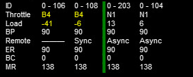
When parameter FullTable is set to False, only the first 6 lines are displayed. Optional parameter LoadUnits defines which is the UoM used for the Load field. Default is AMPS in a metric environment and KILO_LBS in the other cases. Selectable LoadUnits are AMPS, NEWTONS, KILO_NEWTONS, LBS and KILO_KBS.
The screen display can be rotated in 2D cabs adding parameter ORTSAngle ( number ) in the ScreenDisplay block. The angle is in degrees.
Info specific for 3D cabs can be found here .
For every keyboard command related to Distributed Power, a cabview control is also available. Here’s a list of the cabview controls:
- ORTS_DP_MOVE_TO_FRONT
- ORTS_DP_MOVE_TO_BACK
- ORTS_DP_IDLE
- ORTS_DP_TRACTION
- ORTS_DP_BRAKE
- ORTS_DP_MORE
- ORTS_DP_LESS
Here an example of use of one of the controls:
TwoState (
             Type ( ORTS_DP_MOVE_TO_FRONT TWO_STATE )
             Position ( 163.2 378.4 13.75 10 )
             Graphic ( "..\\..\\Common.Cab\\ES44v3\\softkey1trans.ace" )
             NumFrames ( 2 2 1 )
             Style ( WHILE_PRESSED )
             MouseControl ( 1 )
             ORTSDisplay ( 1 )
             ORTSScreenPage ( "2300-0" )
     )
15.1.15. EOT (End of Train device)
See here for full description of EOT features.
Following EOT controls are available for EOT management:
ORTS_EOT_BRAKE_PIPE : displays the value of the brake pipe pressure at last wagon. The display is always enabled (even if the EOT is disarmed), because this display could be available also in other ways; however it is possible to mask the display using a texture driven by the EOT state.
ORTS_EOT_STATE_DISPLAY : may have values from 0 to 5, corresponding to the states listed here
ORTS_EOT_ID : the EOT ID is generated as a 5-digit random number and can be displayed in the cab using this control; entering the ID by the train driver is not supported, as the .cvf files don’t support as of now digital data entry
ORTS_EOT_COMM_TEST : driver command that starts the communication test between locomotive and EOT
ORTS_EOT_ARM_TWO_WAY : driver command passes the EOT from ArmNow to ArmedTwoWay
ORTS_EOT_DISARM : passes the EOT to disarmed state
ORTS_EOT_EMERGENCY_BRAKE (on-off): lets the EOT venting the brake pipe from the last train car.
These controls are available only using the mouse; only The last one can also be operated by the
<Ctrl+Backspace> key combination.
An example of implementation of the above controls can be seen in this picture
The ORTS_EOT_EMERGENCY_BRAKE control can be implemented in the cab by an ON-OFF switch.
An example of implementation of the above controls in a .cvf file follows:
TwoState (
        Type ( ORTS_EOT_COMM_TEST TWO_STATE )
        Position ( 474 385 16.25 10 )
        Graphic ( "..\\..\\Common.Cab\\ES44v3\\softkey5trans.ace" )
        NumFrames ( 2 2 1 )
        Style ( WHILE_PRESSED )
        MouseControl ( 1 )
        ORTSDisplay ( 0 )
        ORTSScreenPage ( "2100-0" )
)
TwoState (
        Type ( ORTS_EOT_DISARM TWO_STATE )
        Position ( 493 385 16.25 10 )
        Graphic ( "..\\..\\Common.Cab\\ES44v3\\softkey5trans.ace" )
        NumFrames ( 2 2 1 )
        Style ( WHILE_PRESSED )
        MouseControl ( 1 )
        ORTSDisplay ( 0 )
        ORTSScreenPage ( "2100-0" )
)
TwoState (
        Type ( ORTS_EOT_ARM_TWO_WAY TWO_STATE )
        Position ( 511.7 385.7 16.25 10 )
        Graphic ( "..\\..\\Common.Cab\\ES44v3\\softkey7trans.ace" )
        NumFrames ( 2 2 1 )
        Style ( WHILE_PRESSED )
        MouseControl ( 1 )
        ORTSDisplay ( 0 )
        ORTSScreenPage ( "2100-0" )
)
MultiStateDisplay (
        Type ( ORTS_EOT_STATE_DISPLAY MULTI_STATE_DISPLAY )
        Position ( 516 314.5 17 5.15 )
        Graphic ( "..\\..\\Common.Cab\\ES44v3\\CommTest.ace" )
        States ( 2 2 1
                State (
                        Style ( 0 )
                        SwitchVal ( 0 )
                )
                State (
                        Style ( 0 )
                        SwitchVal ( 2 )
                )
        )
        ORTSDisplay ( 0 )
        ORTSScreenPage ( "2100-0" )
)
        Digital (
        Type ( ORTS_EOT_ID DIGITAL )
        Position ( 421 313 22 8 )
        ScaleRange ( 0 999999 )
        Accuracy ( 0 )
        AccuracySwitch ( 0 )
        LeadingZeros ( 0 )
        Justification ( 1 )
        PositiveColour ( 1
                ControlColour ( 255 255 255 )
        )
        NegativeColour ( 1
                ControlColour ( 255 255 0 )
        )
        DecreaseColour ( 0
                ControlColour ( 0 0 0 )
        )
        Units ( KILO_LBS )
        ORTSFont ( 6 0 "Arial" )
        ORTSDisplay ( 0 )
        ORTSScreenPage ( "2100-0" )
)
MultiStateDisplay (
        Type ( ORTS_EOT_STATE_DISPLAY MULTI_STATE_DISPLAY )
        Position ( 513.5 328 22.66 5.15 )
        Graphic ( "..\\..\\Common.Cab\\ES44v3\\EOTStatus2.ace" )
        States ( 4 4 1
                State (
                        Style ( 0 )
                        SwitchVal ( 0 )
                )
                State (
                        Style ( 0 )
                        SwitchVal ( 2 )
                )
                State (
                        Style ( 0 )
                        SwitchVal ( 4 )
                )
                State (
                        Style ( 0 )
                        SwitchVal ( 5 )
                )
        )
        ORTSDisplay ( 0 )
        ORTSScreenPage ( "2100-0" )
)
MultiStateDisplay (
        Type ( ORTS_EOT_STATE_DISPLAY MULTI_STATE_DISPLAY )
        Position (  431.4 292.1 9 5  )
        Graphic ( "..\\..\\Common.Cab\\ES44v3\\MaskEOT.ace" )
        States ( 2 2 1
                State (
                        Style ( 0 )
                        SwitchVal ( 0 )
                )
                State (
                        Style ( 0 )
                        SwitchVal ( 2 )
                )
        )
)
TwoState (
        Type ( ORTS_EOT_EMERGENCY_BRAKE TWO_STATE )
        Position ( 53.5 344.2 21.4 42.8 )
        Graphic ( ..\\..\\Common.Cab\\ES44v3\\EOTEmergency.ace )
        NumFrames ( 2 2 1 )
        Style ( ONOFF )
        MouseControl ( 1 )
)
15.1.16. Air Flow Meter
This cabview control is used on some locomotives, particularly in North America, to show the volumetric flow rate of air moving from the main res to the brake pipe during release/recharge. Such an indication can be used to determine when brake pipe charging is complete, measure the amount of brake pipe leakage, and so on. The control will only function on locomotives with air brakes.
Here is an example implementation of ORTS_AIR_FLOW_METER as an analog dial (display types other than analog dials can be used):
Dial (
        Type ( ORTS_AIR_FLOW_METER DIAL )
        Position ( 258 271 1 32 )
        Graphic ( "white_needle.ace" )
        Style ( NEEDLE )
        ScaleRange ( 0 150 )
        ScalePos ( 295 65 )
        Units ( CUBIC_FT_MIN )
        Pivot ( 24 )
        DirIncrease ( 0 )
)
Alternately, a control type of ORTS_TRAIN_AIR_FLOW_METER can be used to display the total air flow rate of all locomotives, useful for distributed power where multiple locomotives can charge the brake pipe simultaneously. Applicable user-defined units are CUBIC_FT_MIN, LITERS_S, LITERS_MIN, and CUBIC_M_S. Cubic meters per second will be used if no units are specified.
15.1.17. Animated 2D Wipers
This control animates the wipers as seen from a 2D cab. Animation is triggered on/off through key V.
Here is an example of a 2D wipers control block within the .cvf file:
ORTSAnimatedDisplay  (
                Type ( ORTS_2DEXTERNALWIPERS MULTI_STATE_DISPLAY )
                Position ( 155 0 331.875 236.25 )
                Graphic ( ..//..//Common.Cab//CabE464_DMI//e464Tergicristallo9.ace )
                ORTSCycleTime ( 1.35 )
                States ( 9 3 3
                        State (
                                Style ( 0 )
                                SwitchVal ( 0 )
                        )
                        State (
                                Style ( 0 )
                                SwitchVal ( 0.11 )
                        )
                        State (
                                Style ( 0 )
                                SwitchVal ( 0.22 )
                        )
                        State (
                                Style ( 0 )
                                SwitchVal ( 0.33 )
                        )
                        State (
                                Style ( 0 )
                                SwitchVal ( 0.44 )
                        )
                        State (
                                Style ( 0 )
                                SwitchVal ( 0.55 )
                        )
                        State (
                                Style ( 0 )
                                SwitchVal ( 0.66 )
                        )
                        State (
                                Style ( 0 )
                                SwitchVal ( 0.77 )
                        )
                        State (
                                Style ( 0 )
                                SwitchVal ( 0.88 )
                        )
                )
        )
ORTSCycleTime is expressed in seconds. The .ace file must contain only the frames related to half cycle, that is if e.g. the wiper moves from left to right and back, only the frames related to the motion from left to right have to be included. For the reverse motion the same frames are used from last to first. SwitchVal can vary from 0 to 1.
15.1.18. Control Labels
The string appearing on the screen when the mouse browses over a command control can be customized with following line, to be added within the control block in the .cvf file:
ORTSLabel ( "string" )
15.1.19. Custom Display Units
Due to the wide variety of railroad equipment across the world, Open Rails may not provide the units of measure needed for a cabview control. In this case, the tokens ORTSUnitsExponent, ORTSUnitsScaleFactor, and ORTSUnitsOffset can be added to the control block in the .cvf file to create the units of measure required for the cab view.
ORTSUnitsExponent ( x ): Raises the value shown by the cab view control to the power of x, which may be used to calibrate nonlinear gauges or complete nonlinear conversions. Fractional and negative values are allowed. For example, an accelerometer gauge with ORTSUnitsExponent ( 0.5 ) would change the accelerometer to be more sensitive to small accelerations, but less sensitive to large acceleration. (However, the values shown would not be in any meaningful units.)
ORTSUnitsScaleFactor ( y ): After accounting for any exponent, multiplies the value shown by the cab view control by a factor of y, allowing for arbitrary conversion of units of measure. For example, a cab view control displaying MILES_PER_HOUR with ORTSUnitsScaleFactor ( 1.467 ) would instead display a value equivalent to feet per second.
ORTSUnitsOffset ( z ): After applying the scale factor, adds z to the value shown by the cab view control. To subtract from the shown value, set z to a negative number. For example, a cab view control with units of BAR and ORTSUnitsOffset ( 0.987 ) would show pressure as absolute pressure, rather than gauge pressure.
Note that while these tokens can be used to convert between many units, it is recommended to use built in Open Rails units wherever suitable.
15.1.20. Multiple screen pages on displays
Modern locomotives have one or more displays in their cabs, and often in such displays it is possible to switch among more screen pages. Fields and controls described in this paragraph enable the implementation of .cvf files with such functionality, for both 2D and 3D cabs.
In the .cvf control blocks following further fields may be optionally present:
ORTSDisplay ( numeric ), indicating the display ID number (from 0 to 7)
to which the control is linked; if such field is missing, display ID number
zero is assumed;

ORTSScreenPage ( alphanumeric-string ) indicating the screen ID string to
which the control is linked; that means that the control is displayed/may be
operated only if its screen is active in that moment; a missing entry
indicates that the control is displayed independently from the selected screen page;
at game start such controls are enabled, plus the ones with line
ORTSScreenPage ( "default" ); more ORTSScreenPage() entries in a single control
are possible.
A new on/off control, called ORTS_SCREEN_SELECT is available, which, in addition to the usual fields and to the optional fields ORTSDisplay and ORTSScreenPage contains one or more of following fields:
ORTSNewScreenPage ( alphanumeric-string numeric ): when the control is clicked,
the controls with field ORTSScreenPage equal to the string of this field and
with field ORTSDisplay equal to the numeric will be displayed on such display
in place of the ones displayed up to that moment. if the numeric is missing within
ORTSNewScreenPage, the involved display is the one referenced in field ORTSDisplay
of ORTS_SCREEN_SELECT.
A further control is available, named ORTS_STATIC_DISPLAY, which is specially devoted to the loading of the background of screen pages (their static part). Here is an example of usage of it:
MultiStateDisplay (
        Type ( ORTS_STATIC_DISPLAY MULTI_STATE_DISPLAY )
        Position ( 246 151 105 16 )
        Graphic ( semproniostatic.ace )
        States ( 1 1 1
                State (
                        Style ( 0 )
                        SwitchVal ( 0 )
                )
        )
                ORTSScreenPage ( "sempronio" )
        )
With this block, the static part of the “sempronio” screen page is loaded on display 0 when such screen becomes the active one.
.cvf files not using fields and controls listed in this paragraph work as usual, with no changes needed.
15.1.21. Further OR cab controls
OR supports the cabview control to open/close the left doors, the right doors and the mirrors.
The control blocks are like the one shown for the cab light. The Type strings are ORTS_LEFTDOOR, ORTS_RIGHTDOOR and ORTS_MIRRORS.
Animation for 2D cab windows is described here .
15.1.22. Cab controls for generic items
OR supports the cabview controls for two generic two-state items.
The cabview controls aree called <ORTS_GENERIC_ITEM1> and
<ORTS_GENERIC_ITEM2>. Their state can be toggled also by respectively
clicking keys <Shift+.> and <Shift+,>.
Sound events are associated, that is:
240: GenericItem1On
241: GenericItem1Off
242: GenericItem2On
243: GenericItem2Off
Animations within the .s file of the locomotive, either stopped/moving or
two-state can be associated to the item state. Linked stopped/moving (wiper type)
animations are named <ORTSITEM1CONTINUOUS> and <ORTSITEM2CONTINUOUS>.
Linked two-state animations (doors type) are named <ORTSITEM1TWOSTATE> and
<ORTSITEM2TWOSTATE>.
The default animation speed for stopped/moving type animations is 8 FPS.
It may be modified with following parameter in the .sd file:
ESD_ORTSCustomAnimationFPS ( 8 )
Examples of use are fan control, open/close of aerodynamic coverages of couplers in high speed trains, menu pages switching.
Animations within the 3D cab .s file are also available, as follows:
ORTS_ITEM1CONTINUOUS
ORTS_ITEM2CONTINUOUS
ORTS_ITEM1TWOSTATE
ORTS_ITEM2TWOSTATE
in analogy to the four animations for the locomotive .s file.
15.1.23. High-resolution Cab Backgrounds and Controls
In MSTS the resolution of the cab background image is limited to 1024x1024; this limitation does not apply in OR as a result of OR’s better handling of large textures.
2D cab backgrounds can reach at least to 3072x3072; however very fine results can be obtained with a resolution of 2560x1600. The image does not have to be square.
2D cab animations have also been greatly improved; you are reminded here that there are two types of animated rotary gauges, i.e. normal gauges and general animations using multiple frames. In this second case in MSTS all of the frames had to be present in a single texture with a max resolution of 640x480. In OR these frames can be as large as desired and OR will scale them to the correct size. In general it is not necessary to use a resolution greater than 200x200 for every frame.
The syntax to be used in the .cvf file is the standard one as defined by MSTS.
To clarify this, the position parameters of a sample needle block are described here.
In the Position statement, the first 2 numbers are the position of the top
left-hand side of the needle texture in cabview units with the needle in the
vertical position. In the Dial type the last 2 numbers are the size of the
needle texture. The last number (50 in the example) controls the scaling of
the needle texture, i.e. changing this changes the size of the needle that OR
displays.
Dial (
    Type ( SPEEDOMETER DIAL )
    Position ( 549 156 10 50 )
    Graphic ( Speed_recorder_needle_2.01.ace )
    Style ( NEEDLE )
    ScaleRange ( 0 140 )
    ScalePos ( 243 115 )
    Units ( KM_PER_HOUR )
    Pivot ( 38 )
    DirIncrease ( 0 )
)
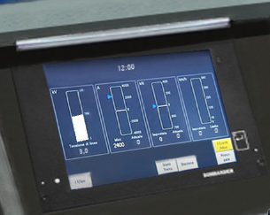
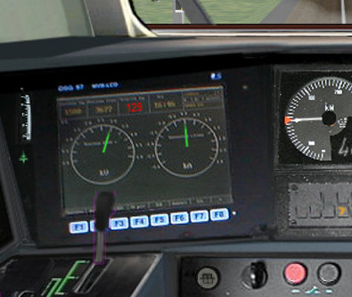
Next is an example of a control animation, this one is a simple 3 frame animation. The examples shown in the following images are the two rotary switches to the right of the two lower brake gauges, both being 3 position. (The left most switch is for the headlights). For these animations the graphic was done at 1600x1600; when each frame was finished it was scaled down to 200x200 and placed into the animation texture. Note the extreme sharpness of these controls in the inset image.
Adding a slight amount of 2x2 pixel blur helps the animation blend into the background better ( this has been done to the gauge needles).
Below is the appropriate part of the CVF. The scaling is controlled by the
last two digits of the Position statement:
TriState (
    Type ( DIRECTION TRI_STATE )
    Position ( 445 397 35 35 )
    Graphic ( Switch_nob_3.0_Transmission.ace )
    NumFrames ( 3 3 1 )
    Style ( NONE )
    MouseControl ( 1 )
    Orientation ( 0 )
    DirIncrease ( 0 )
)
Note that the “Airbrake On” light (on the panel upper left) has also been animated. This is a simple 2 frame animation.
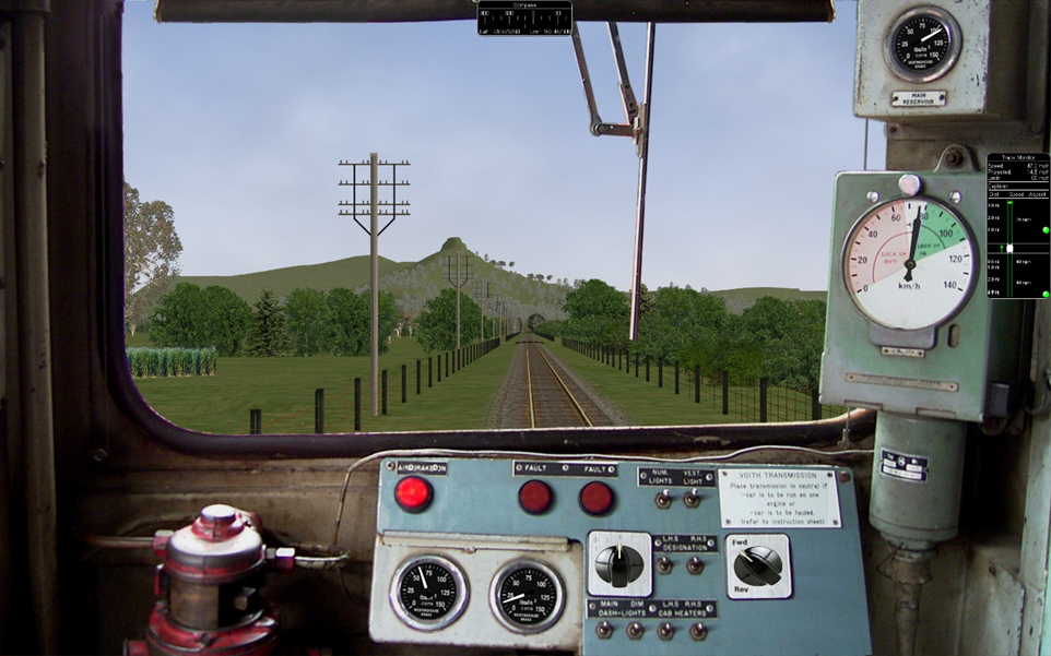
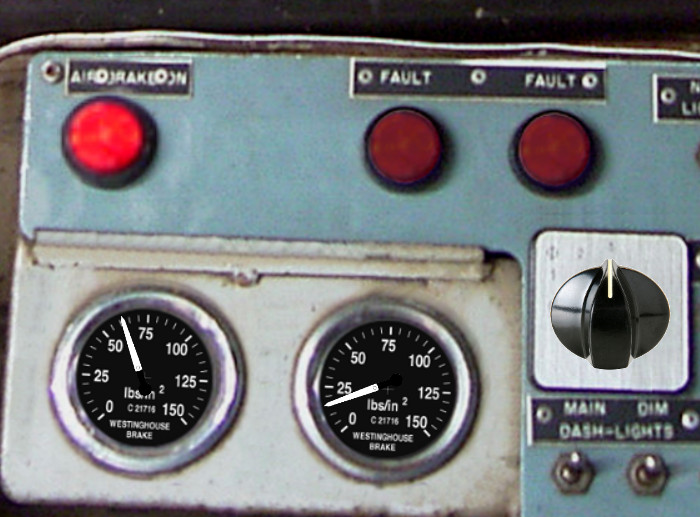
Shown above are two pictures of one hi-res 2D cabview, one showing the whole cab, and the other one showing the detail of some controls. In this example the cab background image used was cut down to 2560x1600. The texture for the Speed Recorder needle is 183x39 and for the brake gauge needles is 181x29, Note the odd number for the width. This is required as OR (and MSTS) assume the needle is in the center of the image. The Reversing and Headlight switch animation frames are 116x116.
There are as yet no specific tools to create these cabviews; a standard image manipulation program to do all textures is required, and to create any new items, e.g. the gauge faces, a standard drawing program can be used. To actual set up the cabview and to position the animations the .cvf file is modified with a standard text editor, and OR is used as a viewer, using a straight section of track on a quick loading route. Through successive iterations one arrives quite quickly at a satisfactory result.
15.1.24. Configurable Fonts
OR supports a configurable font family, with font size selection, and a choice of regular or bold style. More than one font or size can be used in the same cabview. This does not affect the display in MSTS.
An optional line of the form ORTSfont ( fontsize fontstyle "fontfamily" )
must be inserted into the .cvf block of the digital control or digital clock,
where fontsize is a float (default value 10), fontstyle an integer having
the value 0 (default) for regular and 1 for bold, and fontfamily is a
string with the font family name (ex. “Times New Roman”). The default is
“Courier New”. A convenient font, if available, is “Quartz MS” or “Quartz”,
which models a 7-segment display.
Here is an example that displays the digital clock with a 12 pt. bold font using the Sans Serif font family:
DigitalClock (
    Type ( CLOCK DIGITAL_CLOCK )
    Position ( 40 350 56 11 )
    Style ( 12HOUR )
    Accuracy ( 1 )
    ControlColour ( 255 255 255 )
    ORTSFont ( 12 1 "Sans Serif" )
)
It is acceptable if only the first parameter of ORTSFont is present, or only the first two, or all three. Note that you cannot use the MS Cabview editor on the .cvf file after having inserted these optional lines, because the editor will delete these added lines when the file is saved.
15.1.25. Rotation of Gauges and Digital controls
One of the drawbacks of rendering a cabview in 2D is that some parts of it are not shown with a frontal, precisely vertical or horizontal, view. Displaying a vertical gauge or a horizontal digital control on it generates an unrealistic effect. This is the rationale of following entry, to be added within a Gauge or Digital cabview control block in the .cvf file:
ORTSAngle ( 5 )
The number in parenthesis is the angle in degrees with respect to the horizontal (or to the vertical for vertical gauges). Positive values produce counterclockwise rotation.
At the left of the picture an example of a white vertical gauge that has been rotated by 12 degrees
Here an example of a red max speed indication that has been rotated by 5 degrees
Gauges may have Style POINTER or SOLID.
Rotation may be applied, with the same syntax, also to DigitalClock cab controls.
15.1.26. Display and animation of cabview controls in side views of 2D cabs
This is possible adding after the CabViewControls ( ) compound block an ORTSCabviewControls ( ) compound block, that has the same format as the CabViewControls ( ) block. The selection of the CabviewPoint where the control is displayed/animated is performed by a line:
ORTSCabviewPoint ( n )
where n is the ordinal position of the cabview point in the header of the .cvf file.
Here an example:
Tr_CabViewFile (

     CabViewType ( 1 )

     CabViewFile ( CV_Front.ace )
     CabViewWindow ( 0 0 1024 768 )
     CabViewWindowFile ( "" )
     Position ( -0.517699 2.78 8.63 )
     Direction ( 0 0 0 )

     CabViewFile ( CV_Left.ace )
     CabViewWindow ( 0 0 1024 768 )
     CabViewWindowFile ( "" )
     Position ( -0.517699 2.78 8.63 )
     Direction ( 0 -48 0 )

     CabViewFile ( CV_Right.ace )
     CabViewWindow ( 0 0 1024 768 )
     CabViewWindowFile ( "" )
     Position ( -0.517699 2.78 8.63 )
     Direction ( 0 71.5 0 )

     EngineData ( BStE-ET_169a_Jm )

     CabViewControls ( 10
             Dial (
                     Type ( MAIN_RES DIAL )
                     Position ( 163 32 8 30 )
                     Graphic ( CV_Pointer.ace )
                     Style ( POINTER )
                     ScaleRange ( 0 10 )
                     ScalePos ( 227 152 )
                     Units ( BAR )
                     Pivot ( 20 )
                     DirIncrease ( 0 )
             )

             ...

     )

     ORTSCabviewControls ( 12
             TwoState (      Comment( Wiperswitch in right cabviewpoint )
                     Type ( WIPERS TWO_STATE )
                     Position ( 500 165 13 24 )
                     Graphic ( CV_WIPERSSwitch.ace )
                     NumFrames ( 2 2 1 )
                     Style ( ONOFF )
                     MouseControl ( 1 )
                     ORTSCabviewPoint ( 2 )
             )

   ...
     )
In this example ORTSCabviewPoint refers to the 3rd viewpoint ( 0 refers to the main-central viewpoint ) defined in the .cvf header, that is the right side viewpoint.
Note that in Open Rails you may have more than three cabviewpoints defined for 2D cabs.
15.2. 3D cabs
If the locomotive has a 3D cab, it will be selected by default by the simulator.
You can press key <1> to enter the cab. In case locomotive has both 2D and 3D cabs
provided, the key <Alt+1> can be used in order to switch between 2D and 3D cabs.
15.2.1. Development Rules
The 3D cab is described by an .s file, the associated .ace or .dds files, and a .cvf file having the same name as the .s file. All these files reside in a folder named
CABVIEW3Dcreated within the main folder of the locomotive.If the .cvf file cannot be found in the
CABVIEW3Dfolder, the 3D cab is associated with the .cvf file of the 2D cab.Instruments are named with the same conventions as 2D cabs, i.e.
FRONT_HLIGHT,SPEEDOMETER, etc.A cab can have multiple instances of the same instruments, for example multiple clocks or speedometers.
Instruments are sorted based on the order of their appearance in the .cvf file, for example
SPEEDOMETER:0corresponds to the first speedometer in the .cvf file,SPEEDOMETER:1corresponds to the second one.An instrument can have multiple subgroups to make the animation realistic, for example,
TRAIN_BRAKE:0:0andTRAIN_BRAKE:0:1belong to the instrumentTRAIN_BRAKE:0. However, if the instrument is a digital device, the second number will be used to indicate the font size used, for exampleSPEEDOMETER:1:14means the second speedometer (which is digital as defined in .cvf) will be rendered with 14pt font. This may be changed in future OR releases. The important information for a digital device is its location, thus it can be defined as an object with a small single face in the 3D model.
Animation ranges must be in agreement with the .cvf file
Within the Wagon section of the .eng file a block like the following one has to be generated:
ORTS3DCab(
    ORTS3DCabFile ( Cab.s )
    ORTS3DCabHeadPos ( -0.9 2.4 5.2 )
    RotationLimit ( 40 60 0 )
    StartDirection ( 12 0 0 )
)
If also a rear cab is present, a second
ORTS3DCabhas to be added, as follows:ORTS3DCab( ORTS3DCabFile ( Cab.s ) ORTS3DCabHeadPos ( 0.9 2.4 5.2 ) RotationLimit ( 40 60 0 ) StartDirection ( 12 180 0 ) )
Alternate 3D cab viewpoints may be added, as in the example here below:
ORTSAlternate3DCabViewPoints
                   (
  ORTSAlternate3DCabViewPoint(
     ORTS3DCabFile ( Cab.s )
     ORTS3DCabHeadPos ( 0.9 2.4 5.2 )
     RotationLimit ( 40 60 0 )
     StartDirection ( 12 0 0 )
                  )
  ORTSAlternate3DCabViewPoint(
    ORTS3DCabFile ( Cab.s )
    ORTS3DCabHeadPos ( -0.8 2.4 5.2 )
    RotationLimit ( 40 60 0 )
    StartDirection ( 12 30 0 )
                  )
                  )
To switch between alternate cab viewpoints
Ctrl-Shift-1must be pressed. If there aren’t alternate viewpoints defined, and if there is no rear cab, pressingCtrl-Shift-1toggles between the base viewpoint and a symmetrical one on the longitudinal axis.
It is also possible to animate the wipers, by inserting into the .s file an animation named
EXTERNALWIPERS:0:0Gauges of solid type have to be named
AMMETER:1:10:100; where the three numbers indicate that this is the second ammeter, that it has a width 10 mm, and a maximum length of 100 mm. The color and direction/orientation follow those defined in .cvf files.Digits for 3D cabs can now use custom ACE files; e.g. name the part as
CLOCK:1:15:CLOCKS. This will draw the second clock with 15mm font dimension, with theCLOCKS.ACEfile inCABVIEW3Dcontaining the font. If no ace is specified, the default will be used.Mirrors and doors can be operated from 3D cabs. The names used are
LEFTDOOR,RIGHTDOORandMIRRORS.Animation for 3D cab windows is described here .
like the 2D cabs, also 3D cabs can have a night version. Night textures, named like the corresponding day textures, must be located within a
NIGHTsubfolder of theCABVIEW3Dfolder. To enable night cabs an.sdfile with the same name as the shape file of the 3D cab must be present in theCABVIEW3Dfolder. This.sdfile has a standard format and must contain following line:ESD_Alternative_Texture ( 256 )
How to control the view in a 3D cab is described here.
A demo trainset with a 3Dcab, that may be useful for developers, can be downloaded from: http://www.tsimserver.com/Download/Df11G3DCab.zip
15.2.2. A Practical Development Example For a Digital Speedometer
Let’s suppose you wish to create a digital speedometer using a size 14 font.
To explain it in gmax language, you must have an object called SPEEDOMETER
in the cab view and it must be comprised of at least one face.
As the sample cab has only one digital speedometer, it can be named
SPEEDOMETER_0_14.
The number 0 indicates that this is the first speedometer gauge in the cab and the number 14 indicates the size of the font to display. Note that an underscore is used to separate the numbers as the LOD export tool does not support the use of colons in object names when exporting. More on this later.
The speed does not display where the face for the SPEEDOMETER object is
located but where the pivot point for the SPEEDOMETER object is located.
Normally you would place the SPEEDOMETER object somewhere in the cab where
it will not be seen.
With the SPEEDOMETER_0_14 object selected in gmax, go to the Hierarchy
tab, select Affect Pivot Only and click Align to World to reset the
orientation to world coordinates. Then use the Select and Move tool to move
the pivot to where in the cab you wish the numerals to appear. As you have
aligned the pivot point to World coordinates the numerals will display
vertically. As most locomotive primary displays are normally angled you may
have to rotate the pivot point so that it aligns with the angle of the
display screen.
Export the .S file for the cab as usually.
You will then have to uncompress the .s file for the cab using Shape File Manager or the .S file decompression tool of your choice.
Then open the .S file with a text editor and search for the letters “speed”
until you find the first instance of SPEEDOMETER_0_14 and change it to be
SPEEDOMETER:0:14. Search again and find the second instance of
SPEEDOMETER_0_14 and change that also to SPEEDOMETER:0:14. Save the
.S file in the text editor.
Now just one more thing. Download the DF11G3DCab demo trainset. In the
CABVIEW3D folder of that download you will find an ace file called
SPEED.ACE. Copy that file and paste it into the CABVIEW3D folder
for your model.
Now, open OR and test your speedometer.
15.2.3. FUEL_GAUGE for steam locomotives
The FUEL_GAUGE dial is available also for steam locomotives. It may be used both to display a fuel level for oil burning steam locomotives (also in 2D cabs), and to animate the coal level in a tank loco. Default unit of measure is Kg; alternate unit of measure may be LBS. Here below is an example of an entry for a 3D cab:
Dial (
Type ( FUEL_GAUGE DIAL )
Style ( POINTER )
ScaleRange ( 0 5000 )
Units ( LBS )
)
15.2.4. Distributed power display
Following info applies to the creation of a distributed power display in 2D cabs, in addition to what is described here for 2D cabs.
In the 3Dcab .s file an ORTS_DISTRIBUTED_POWER object must be defined, with the same syntax rules of the digitals, so e.g. ORTS_DISTRIBUTED_POWER:0:8:DPI , where 8 is the selected character font size and DPI is the DPI.ace texture associated.
In the folder where the 3D cab files are located (usually CABVIEW3D) such file DPI.ace
must be present. A sample file for that can be found in
Documentation\SampleFiles\Manual\DPI.zip . Here is how such file looks like
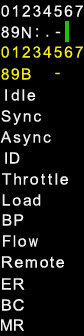
Customizations for such file are possible following these rules:
Horizontal/vertical ratio must be kept
The first four lines must have the characters centered in their rectangle.
From the 5th line on characters may be also spaced in a thicker way (as is for the
Idlestring in the above picture)From the 5th line on strings may be replaced bo strings in other national languages, provided that the new strings aren’t wider than the original ones.
It should be possible to have a transparent background if preferred.
Except for the first column, fields in the 3D distributed power display are always with center alignment.
15.2.5. Alignment for digital controls
For backwards compatibility reasons, Justification ( 1 ), Justification ( 2 ) and
Justification ( 3 ) all lead to a left alignment of the digital in 3Dcabs.
Justification ( 5 ) must be used for center alignment, and Justification ( 6 )
must be used for right alignment. Justification ( 4 ) leads to left alignment.