9. Further Open Rails Rolling Stock Features
For a full list of parameters, see Developing OR Content - Parameters and Tokens
9.1. Train Engine Lights
OR supports the whole set of lights accepted by MSTS, MSTS-bin, and adds many new options to enhance the variety and complexity of lighting systems that can be recreated.
9.1.1. Lights with multiple conditions
In the original MSTS light implementation, each light could only have one set of activation conditions. If the same light were to be activated in multiple situations, (for example, a light which should turn on for both the front and rear units) the entire light would need to be included twice, just with different conditions.
Open Rails now allows for a single light to have multiple Conditions () blocks.
If any one set of conditions is fulfilled, the light will be enabled. If no conditions
are specified, the light will be assumed to be on always. An example of how this can
be used to simplify Lights implementation is included below:
Light   (
        comment( Nose light bright )
        Conditions      (
                Headlight ( 3 )
                Unit ( 2 )
        )
        FadeIn  ( 0.5 )
        FadeOut ( 0.5 )
        States  (       1
                State   (
                        LightColour ( FFffffe6 )
                        Radius ( 0.6 )
                        Position ( 0.0 4.12 6.55 )
                )
        )
)
Light   (
        comment( Nose light bright DPU )
        Conditions      (
                Headlight ( 3 )
                Unit ( 4 )
        )
        FadeIn  ( 0.5 )
        FadeOut ( 0.5 )
        States  (       1
                State   (
                        LightColour ( FFffffe6 )
                        Radius ( 0.6 )
                        Position ( 0.0 4.12 6.55 )
                )
        )
)
This set of two lights can be simplified to one light like this:
Light   (
        comment( Nose light bright )
        Conditions      (
                Headlight ( 3 )
                Unit ( 2 )
        )
        Conditions      (
                Headlight ( 3 )
                Unit ( 4 )
        )
        FadeIn  ( 0.5 )
        FadeOut ( 0.5 )
        States  (       1
                State   (
                        LightColour ( FFffffe6 )
                        Radius ( 0.6 )
                        Position ( 0.0 4.12 6.55 )
                )
        )
)
Both of these snippets produce the same result: a light that turns on when the
headlights are bright and the unit is first, or the last unit reversed (ie:
distributed power). However, by specifying multiple conditions, the second
implementation takes up much less space and guarentees that both modes of the
light have the exact same States. There is no hard limit on the number
of conditions a light can have.
9.1.2. Lights attached to shape sub-objects
The standard lighting configuration attaches all lights to the main body of the locomotive or wagon. While this allows lights to move and rotate as the vehicle itself moves, the approach has proven insufficient for more complicated rail vehicles such as articulated steam locomotives.
To facilitate lighting on such locomotives and wagons, Open Rails now allows
for attachment of lights to any sub-object of the shape file. With the
ShapeHierarchy token placed in a Light () block, the object the light
will rotate and translate with can be defined using the hierarchy name of said
object. Tools such as Shape Viewer can be used to determine the hierarchy name
of a particular object in the shape file. For example, “BOGIE1” is the standard
name for the frontmost bogie. A light attached to this bogie could be created
like so:
Light   (
        comment( CNDR Side Front Truck Light )
        ShapeHierarchy ( "BOGIE1" )
        States  (       1
                State   (
                        LightColour ( 91fedf91 )
                        Position ( -1.427 0.583 -0.330 )
                        Azimuth ( -90 -90 -90 )
                        Radius ( 0.2 )
                )
        )
)
Be aware that the Position of a light is measured relative to the center of
the object to which the light is attached, not to the center of the locomotive
itself. Furthermore, the naming of shape parts is not consistent between all
shape files. If the shape name entered in ShapeHierarchy is invalid, a
warning will be produced in the log file and the light will attach to the
main body of the locomotive or wagon.
If ShapeHierarchy is not specified in a light, the light will attach
to the main body of the locomotive or wagon by default.
9.1.3. Open Rails specific lighting conditions
Open Rails also adds a set of new lighting conditions which offer additional
flexibility in creating detailed light behaviors. Note that each of these
must be inside the Conditions () block of a Light () in the .eng/.wag
file to function. All conditions are optional and can be mixed and matched
as needed, though only one of each condition can be included per conditions
block!
9.1.3.1. Battery
The light condition ORTSBattery allows a light to respond to the state of
the battery subsystem. The valid settings
and associated conditions for the light to turn on are as follows:
ORTSBattery ( 0 )Battery state is ignored (default)ORTSBattery ( 1 )Battery switch must be onORTSBattery ( 2 )Battery switch must be off
9.1.3.2. Friction Brakes
The Brake condition can be used to create brake indicator lights
which turn on or off when the friction brakes are applied. Dynamic brakes
have no effect.
Brake ( 0 )Brake application/release is ignored (default)Brake ( 1 )Brakes must be releasedBrake ( 2 )Brakes must be applied
9.1.3.3. Reverser
Reverser is a very powerful condition that gives lights the ability
to be enabled by the selected direction of travel. Note that a flipped
locomotive or wagon will automatically flip the sensed reverser setting
to ensure lights shine in the correct direction. Also, steam locomotive
cutoff values between -10% and 10% will be detected as ‘neutral’.
Reverser ( 0 )Reverser direction is ignored (default)Reverser ( 1 )Reverser direction must be forwardReverser ( 2 )Reverser direction must be reverseReverser ( 3 )Reverser direction must be neutralReverser ( 4 )Reverser direction must be forward or reverseReverser ( 5 )Reverser direction must be forward or neutralReverser ( 6 )Reverser direction must be reverse or neutral
9.1.3.4. Passenger Doors
Many pieces of passenger rolling stock have indicator lights to inform
the crew passenger doors are open. The
Doors condition is suited to this type of lighting.
Doors ( 0 )Passenger doors are ignored (default)Doors ( 1 )Passenger doors must all be closedDoors ( 2 )Passenger doors on the left must be openDoors ( 3 )Passenger doors on the right must be openDoors ( 4 )Passenger doors on both sides must be openDoors ( 5 )Passenger doors on either the left or right must be open
9.1.3.5. Horn (Automatic Flashing Ditch Lights)
Open Rails now supports the ability to configure flashing ditch lights
(or any other type of horn activated auxiliary lighting)
with the Horn light condition. When the horn is sounded, lights
with the horn condition will (de)activate, and remain (de)activated
for a time after the horn stops sounding. The standard timer is 30
seconds, but can be changed by placing a ORTSHornLightsTimer
token in the engine() section of the locomotive with flashing lights.
If ORTSHornLightsTimer( 0s ) is set, the lights will only activate
while the horn is sounding and immediately stop afterward.
Horn ( 0 )Horn state is ignored (default)Horn ( 1 )Horn must not have been sounded recentlyHorn ( 2 )Horn must have been sounded recently
Note that the solid ditch lights state should use Horn(1) to
prevent these lights overlapping the flashing state. An example
implementation of a flashing ditch light’s conditions (many other
details removed for clarity) is provided below:
Light   (
        comment( Right ditch light )
        Conditions      (
                Headlight ( 3 )
                Unit ( 2 )
                Horn ( 1 )
        )
        States  (       1
                State   (
                        LightColour ( FFFFFFFF )
                        Radius ( r )
                        Position ( x y z )
                )
        )
)
Light   (
        comment( Right ditch light Flashing )
        Conditions      (
                Headlight ( 3 )
                Unit ( 2 )
                Horn ( 2 )
        )
        States  (       2
                State   (
                        LightColour ( FFFFFFFF )
                        Radius ( r )
                        Transition ( 1 )
                        Duration ( 0.5 )
                        Position ( x y z )
                )
                State   (
                        LightColour ( FFFFFFFF )
                        Radius ( r )
                        Transition ( 1 )
                        Duration ( 0.5 )
                        Position ( x y z )
                )
        )
)
9.1.3.6. Bell (Automatic Flashing Ditch Lights)
Similar to Horn, the Bell condition is useful for replicating
systems with flashing lights activated by the bell, though this is
less common than using the horn. Like with the horn, a timer can be
set to keep the lights activated for a time after the bell starts ringing.
Unlike with the horn, this timer is set to 0 seconds by default, meaning
the lights will only remain (de)activated while the bell is currently ringing.
If a timer is desired, engine(ORTSBellLightsTimer can be used in
the locomotive’s .eng file.
Bell ( 0 )Bell state is ignored (default)Bell ( 1 )Bell must not have been ringing recentlyBell ( 2 )Bell must have been ringing recently or is ringing now
9.1.3.7. Multiple Unit Configuration (Locomotives Only)
Some MU systems send headlight signals through the wires connecting locomotives,
but do not or cannot send these signals through wagons/coaches to remote
locomotives (eg: distributed power, banking locomotives, etc.). The MU
light condition allows for some flexibility in adjusting light behavior depending
on a locomotive’s physical connection to the lead locomotive (or lack thereof).
While meant for locomotives only, wagons are always treated as remote locomotives
for the purposes of calculation.
MU ( 0 )Locomotives’s connection to the lead locomotive is ignored (default)MU ( 1 )Locomotive must be the lead locomotive itselfMU ( 2 )Locomotive must be in the same group of locomotives as the lead locomotiveThis condition will also be fulfilled for the lead locomotive itself.
MU ( 3 )Locomotive must be in a different group to the lead locomotive
9.1.4. Multiple type locomotive light glows
9.1.4.1. Introduction
As a default all OR (and MSTS) locomotives use the same texture to reproduce the glow of their lights. This however doesn’t allow to easily implement non-round or LED array lights, neither to provide special glowing effects.
This feature allows to specifiy customized light glow textures for the locomotives.
If nothing is specified, the standard light glow texture is used. Moreover in the Content
folder, two light glow textures are present: the “historical” one, and a new one,
more realistic. As a default the “historical” light glow texture is used, for backwards
compatibility; however adding a line to the Lights block in the .eng file the “new” light
glow texture is taken. Customized light glow textures can be either used for all lights
of a loco, or only for a subset of them. Different lights in the same locomotive
may have different customized light glow textures.
9.1.4.2. Detailed spec
In the
Contentfolder there is the defaultLightGlow.png, which is displayed if no changes are done to the .eng file.In such folder there is also an
ORTSLightGlow.png, which is maybe more realistic.adding a line within the .eng file it is possible to select either ORTSLightGlow.png or any other picture with extension
.aceor.dds.Here an example for the legacy Acela loco:
Lights  ( 17
        ORTSGraphic ( "ORTSLightGlow.png" )
              Light     (
                      comment( Sphere of light )
                      Type      ( 1 )
                      Conditions        (...
The code first searches for the file by building its directory starting from the directory of the .eng file; in this case the line could be e.g.:
ORTSGraphic ( "ORTSAcelaLightGlow.dds" )
The
ORTSGraphicline can be added also for one or moreLight()blocks. In that case the file is used only for the related Light block. Here an example:Light ( comment( Head light outer right bright ) Type ( 0 ) Conditions ( Headlight ( 3 ) Unit ( 2 ) ) FadeIn ( 0.5 ) FadeOut ( 0.5 ) Cycle ( 0 ) States ( 1 State ( Duration ( 0.0 ) LightColour ( ffffffff ) Position ( -0.5922 2.4037 9.63208 ) Azimuth ( 0.0 0.0 0.0 ) Transition ( 0 ) Radius ( 0.60 ) Elevation ( -50 -50 -50 ) ) ) ORTSGraphic (BigLightGlow.dds) )
OR searches for the file as it does for the general file for all lights, as explained above. If the
ORTSGraphicline is present both at the top of theLights()and also in someLight()subblock, the line present in the subblock prevails. So it is possible to have an .eng-specific graphic for all the lights, except the ones that have an ownORTSGraphicline.
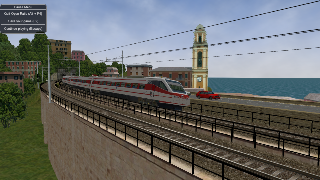
9.2. Tilting trains
OR supports tilting trains. A train tilts when its .con file name contains the
tilted string: e.g. ETR460_tilted.con.
9.3. Features to assist content creation
OR now includes some features that don’t change the functionality of rolling stock, but simplify some steps of the content creation process or allow more control over content than was previously possible. The goal of these features is to save content creators’ time, give additional power to creators, and to simplify the installation process for end users.
9.3.1. Automatic wagon size calculation
Determining the appropriate values to enter in the Size ( w, h, l ) parameter of an engine or
wagon can be tedious, as reasonable settings for the simulated width, height, and length of rolling
stock depend on measurements of the 3D model used. Many content creators have entered largely
arbitrary values of width and height into the size parameter, only adjusting the length value to
give correct coupler alignement.
To simplify this process, and produce more reasonable dimensions for rolling stock, OR can now
automatically calculate the dimensions of rolling stock based on the shape file used. Enter
ORTSAutoSize in the Wagon section of an engine or wagon to allow OR to determine
the width, height, and length of the rolling stock based on the bounding info of the shape file,
ignoring any values entered manually in the MSTS Size parameter.
Additionally, ORTSAutoSize accepts 3 (optional) arguments, default units in meters, corresponding to
offsets from the shape’s width, height, and length respectively. For example,
ORTSAutoSize ( 0.1m, -0.2m, -0.18m ) would tell OR to automatically determine the wagon’s dimensions
from the shape file or ORTSShapeBounds (see next paragraph), then subsequently add 0.1 meters to the
width, subtract 0.2 meters from the height, and subtract 0.18 meters from the length, using the resulting
values to set the simulated size of the wagon. In most cases, the width and height arguments can be set to
0, and the length argument adjusted to produce the desired coupler spacing. If no arguments are specified
(ie: ORTSAutoSize () was entered in the Wagon section) then all three offsets are assumed to be 0 meters.
Inspecting the shape file to determine its size requires additional processing time, but this
step can be skipped by providing the data directly with the ORTSShapeBounds parameter.
Enter the minimum and maximum bounds of the shape in the format ORTSShapeBounds ( minX minY minZ
maxX maxY maxZ ), where the first 3 values give the minimum bounds (leftmost, rearmost, and lowest
points) and the second 3 values give the maximum bounds (rightmost, frontmost, highest points) of the
vertices in the shape, in meters by default. These 6 values can be determined automatically by shape
viewing programs, saving time by only running the calculation once, at the disadvantage of not
updating if the shape changes. If verbose eng/wag configuration messages are enabled, OR will also
log the settings it calculated for ORTSShapeBounds when ORTSAutoSize is used.
Note that the automatic bounding method has further limitations that may require use of ORTSShapeBounds
or prevent use of auto sizing entirely. Automatic bounding calculation uses the nearest LOD of
the main shape file and attached freight animations. LODs for further distances have no effect
on the automatic sizing. Freight animations using the ShapeHierarchy feature are also skipped
due to potential unintended behaviors. Shape descriptor overrides
are also not considered at this phase, so if any changes are made in the .sd file, this feature may not
provide good results. This method also works best for rolling stock with standard buffers/couplers on
each end. Automatic sizing generally can’t produce reasonable results for articulated rolling stock.
And should something go wrong with the shape file causing automatic sizing to fail, OR will revert to
the values entered in the Size parameter.
9.3.2. Improved wagon alignment tools
Many MSTS and OR creators have encountered rolling stock shapes that were not correctly aligned,
resulting in couplers/buffers clipping at one end of the wagon and separating at the other end.
Normally, this would require inspecting the 3D model to determine exactly how off-center it was
and carefully setting the Z value of CentreOfGravity ( x, y, z ) to “nudge” the wagon shape
until it is centered.
In some cases, this approach could still be insufficient as the Z offset is limited to 2 meters in
order to prevent unusual behaviors with some MSTS models that used unreasonably large Z offsets.
To facilitate models that need large offsets without introducing errors, OR now accepts this offset
with the parameter ORTSShapeNudge ( z ), which can be set to any length offset without limit.
However, this does not entirely replace CentreOfGravity. The Y (height) value of the CoG is
still used by the physics system and should still be defined. In this case, simply use
CentreOfGravity ( y ) where y is the CoG height in meters (or other units, as desired).
Unlike entering all 3 values for the CoG, entering only the Y value will NOT affect the alignment
of the 3D model, allowing the “physical” CoG to be entered separately from the “visual” CoG.
And, for the sake of simplicity, it may be desired to just center the 3D model lengthwise
such that the couplers/buffers are equidistant from the centerpoint of the model. To make this
specific case easier, OR now includes the ORTSAutoCenter parameter. When ORTSAutoCenter ( 1 )
is included in the Wagon section of an engine or wagon, OR will use the shape bounding box given
by ORTSShapeBounds or calculated automatically from the shape file to determine the exact
Z value of CentreOfGravity required to re-center the shape in the simulation. This will overwrite
the manually entered Z component of CentreOfGravity ( x y z ) but will not change the X or Y
components. Should no re-centering be required, none will be applied.
Some rolling stock will not align correctly when auto-centered. As with ORTSAutoSize, this
feature should be employed on rolling stock with standard buffers or couplers, and will
not produce suitable results for articulated rolling stock or stock with different coupler
types at each end. Only the highest detail LOD of the main shape and freight animations are
used, the .sd file is not checked. If the process fails, a warning will be written to the
log and the automatic calculation will be skipped.
9.3.3. Advanced articulation control
A wide variety of modern rolling stock uses articulation, in which multiple rail vehicles share a single “Jacobs Bogie”. Open Rails offers partial support for such passenger and freight units by allowing one wagon to include a bogie in its 3D model while the next wagon removes the bogie from its 3D model. Ideally, OR will then add an invisible bogie to the end of the wagon without the bogie to emulate “sharing” the bogie with the previous wagon.
However, this automatic system is limited. OR will check for wheels in the wagon’s 3D model and will assume the wagon is articulated at one end if there are no wheels towards that end of the 3D model. This approach will only be used on 3D models with 3, 2, or 0 axles (the 1-axle case is excluded for compatibility reasons) and won’t be used on locomotives. In some cases, this approach will result in false negative or false positive detection of articulation. Should the automatic articulation method not produce the expected track following behavior, it is now possible to manually define whether a wagon or engine should use the articulation behavior.
To forcibly enable the articulation behavior at the front of the rail vehicle, use
ORTSFrontArticulation ( 1 ) and at the rear use ORTSRearArticulation ( 1 ).
Conversely, use ORTSFrontArticulation ( 0 ) or ORTSRearArticulation ( 0 ) to
force disable articulation behavior. Articulation should generally be enabled on the
‘floating’ end(s) of a vehicle, where a bogie or wheels are not present in the 3D
model, and disabled on the end(s) that have wheels. Entering a value of -1 provides
the default (automatic) behavior.
9.4. Freight animations and pickups
9.4.1. OR implementation of MSTS freight animations and pickups
OR supports the freight animations as MSTS does (refueling of water, coal and diesel); when refueling from a water column the animation of the column arm is supported; coal level in the tender of the player loco decreases with consumption and increases when refueling.
The following pickup parameters are taken into consideration by OR for the MSTS animations:
Pickup type
Speed range
Anim length
The pickup animation frame rate is computed as the ratio between the number of frames defined in the .s file, divided by the Anim length.
As in MSTS, Freight Animations are treated differently for tenders than for other vehicles.
Tenders:
First numeric parameter: shape vertical position when full, relative to its origin, in meters
Second numeric parameter: shape vertical position when empty, relative to its origin, in meters.
Third numeric parameter: set to any positive value, or omitted, causes the shape to drop - see below.
As long as the second parameter is lower than the first and the third parameter is either omitted or has a non-zero value, the shape will drop, based on fuel consumption.
If the second parameter is not lower than the first, no movement will take place irrespective of the 3rd parameter.
Other Vehicles:
The numeric parameters are not used.
9.4.2. OR specific freight animations and pickups
9.4.2.1. General
In addition to the support of the MSTS freight animations, Open Rails provides a large extension for freight animations (called OR freightanims below) and pickups.
Following are the native features Open Rails offers:
two types of OR freightanims: continuous and static
continuous OR freightanims are related to commodity loads, like coal, or stones: the load level in the trainset varies accordingly to the amount of load
static OR freightanims are in fact additional shapes that can be attached to the main trainset shape. Such shapes may also include an animation (independent from train behaviour);
both types of OR freightanims can be present in the same trainset, and can coexist with original MSTS freight animations
both types of OR freightanims can be related to locomotives or wagons
more than one static OR freightanim can be present in a single trainset
a wagon can be loaded with different commodities in different moments
commodities can be loaded (in pickup stations) and unloaded (in unloading stations).
wagons supporting continuous OR freightanims may be provided with a physical animation that is triggered when unloading the wagon (like opening its bottom or fully rotating)
OR freightanims are defined with an
ORTSFreightAnims ()block within the .wag or within the wagon section of an .eng file. It is suggested that this block be defined within an include file as described here.
9.4.2.2. Continuous OR Freightanims
A description of this feature is best achieved by showing an example of an
include file, (in this case named AECX1636.wag and located in an Openrails
subfolder within the wagon’s folder). Note that the first line of the file must
be blank.:
include ( ../AECX1636.wag )

Wagon (
    ORTSFreightAnims
    (
        MSTSFreightAnimEnabled (0)
        WagonEmptyWeight(22t)
        IsGondola(1)
        UnloadingStartDelay (7)
        FreightAnimContinuous
        (
            IntakePoint ( 0.0 6.0 FreightCoal )
            Shape(Coal.s)
            MaxHeight(0.3)
            MinHeight(-2.0)
            FreightWeightWhenFull(99t)
            FullAtStart(0)
        )
        FreightAnimContinuous
        (
            IntakePoint ( 0.0 6.0 FuelCoal )
            Shape(Coal.s)
            MaxHeight(0.3)
            MinHeight(-2.0)
            FreightWeightWhenFull(99t)
            FullAtStart(0)
        )
    )
)
The ORTSFreightAnims block is composed by a set of general parameters
followed by the description of the OR freightanims. Here below the general
parameters are described:
MSTSFreightAnimEnabledspecifies if eventual MSTS freight animations within the trainset are enabled (1) or not (0). This is useful if one wants to use a wagon where the load is already shown with a (static) MSTS freight animation. In such a case the MSTS freight animation must be disabled, to use the OR freightanim, that allows to modify the vertical position of the freight shape.WagonEmptyWeightdefines the mass of the wagon when empty. If the parameter is missing, the weight of the load is not considered and the weight of the wagon is always the value present in the root .eng file.IsGondolaspecifies (in case it is set to 1) if the load has to be rotated during unloading, as happens in a gondola wagon. If absent the parameter is set to 0.UnloadingStartDelayspecifies, if present, after how many seconds after pressing of the T key the unloading starts. This is due to the fact that some seconds may be needed before the wagon is set in a unloading layout. For example, a gondola must rotate more than a certain number of degrees before the load begins to fall down.
There may be more than one FreightAnimContinuous subblock, one for each
possible load type. The parameters of the subblock are described below:
IntakePointhas the same format and the same meaning of the IntakePoint line within the standard MSTS freight animations. Following types of loads are accepted: FreightGrain, FreightCoal, FreightGravel, FreightSand, FuelWater, FuelCoal, FuelDiesel, FuelWood, FuelSand, FreightGeneral, FreightLivestock, FreightFuel, FreightMilk, SpecialMail. All these types of loads can be defined. Some of the pickup types (to right of FuelDiesel) need to be coded in W text files.Shapedefines the path of the shape to be displayed for the loadMaxHeightdefines the height of the shape over its 0 position at full loadMinHeightdefines the height of the shape over its 0 position at zero loadFreightWeightWhenFulldefines the mass of the freight when the wagon is full; the mass of the wagon is computed by adding the mass of the empty wagon to the actual mass of the freightFullAtStartdefines wether the wagon is fully loaded (1) or is empty at game start; if there are more continuous OR freightanims that haveFullAtStartset to 1, only the first one is considered.
As already outlined, the wagon may have a physical animation linked with the unload operation.
In a gondola this could be used to rotate the whole wagon, while in a hopper it could be used to open the bottom of the wagon.
The base matrix within the wagon shape that has to be animated must have a name
that starts with UNLOADINGPARTS. There may be more than one, like
UNLOADINGPARTS1, UNLOADINGPARTS2 and so on. Its frame rate is fixed,
and is 1 frame per second as for the other types of OR trainset animations.
To define a pickup point as an unload point, its shape must be inserted in the .ref file of the route as a pickup object . Here is an example of the .ref block:
Pickup (
    FileName ( rotary_dump.s )
    Shadow ( DYNAMIC )
    Class ( "Track Objects" )
    PickupType ( _FUEL_COAL_ )
    Description ( "Rotary dumper" )
)
When laying it down in the route with the MSTS Route Editor, its fill rate must be set to a negative value.
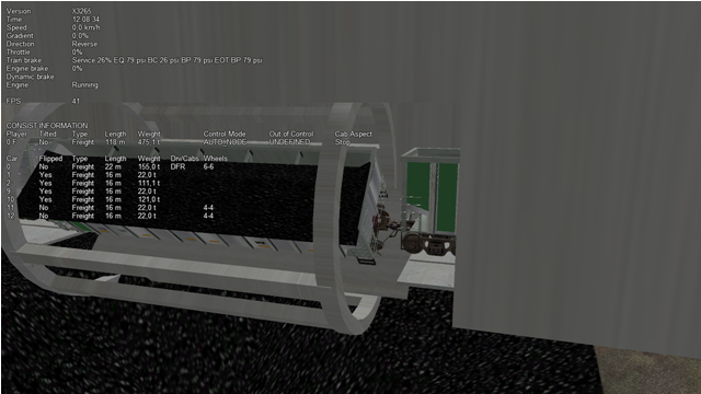
Such a pickup (which in reality is an unloader) may be animated too. The base matrix
within the wagon shape that has to be animated must have a name
that starts with ANIMATED_PARTS. There may be more than one, like
ANIMATED_PARTS1, ANIMATED_PARTS2 and so on. As for the
MSTS standard pickups, the pickup animation frame rate is computed as the ratio
between the number of frames defined in the .s file, divided by the Anim length.
By combining a physical animation of the wagon with an unloader animation effects like that of a wagon within a rotary dumper may be achieved, as seen in the picture below.
Loading and unloading a trainset is triggered by pressing the <T> key when
the trainset is at the pickup/unloader location.
9.4.2.3. Static OR Freightanims
Only the two general parameters shown below are used for static OR freightanims:
MSTSFreightAnimEnabled (0)
WagonEmptyWeight(22t)
The subblock (to be inserted within the ORTSFreightAnims block) has the
following format:
FreightAnimStatic
(
    SubType(Default)
    Shape(xxshape.s)
    Offset(XOffset, YOffset, ZOffset)
    FreightWeight(weight)
    Flip()
    Visibility ( "Outside,Cab2D,Cab3D" )
)
Where:
SubTypeis not currently usedShapeis the path of the shape file.XOffset,YOffsetandZOffsetare the offsets of the shape with respect to its zero position, and are useful to place the shape precisely.FreightWeightis the weight of the specific load. This weight is added to theWagonEmptyWeightvalue (if present) to provide the total weight of the wagon. If more static OR freightanims are present, each of their weights is added to define the total weight of the wagon.Flip(), if present, flips the shape around its pivot point.Visibility, if present, changes the default visibility of the static freightanim. Default is visible only from outside cameras and from any inside camera of locomotives different from the one hosting the static freightanim. If substringOutsideis present, the static freightanim is visible from outside cameras and from any inside camera of locomotives different from the one hosting the static freightanim; ifCab2Dis present, the static freightanim is visible from the 2D cabview camera of loco hosting the freightanim; ifCab3Dis present, the static freightanim is visible from the 3D cabview camera of loco hosting the freightanim. 1, 2 or 3 of such substrings may be inserted in theVisibilityline allowing for any combination of visibility.
Because more static OR freightanims may be defined for a wagon, in the case of a container wagon that is able to carry more than one container, even as a double stack, it is possible to use a static OR freightanim for each container, defining its position within the wagon.
9.4.3. Physics Variation with Loads
9.4.3.1. Variable Loads (Continuous Freight Animation)
Open Rails supports the variation of key physics parameters in the wagon as the load varies within the wagon. The parameters which can be changed are:
Mass
Brake and handbrake force
Friction (general and wind)
Centre of Gravity (impacts on curve performance)
Drive wheel weight (impacts upon locomotive adhesve weight)
Locomotives and tenders that are also configured will have their loads, and the above physics parameters adjusted as coal and water is used. The adhesive weight (Drive wheel weight) will also be adjusted as the load changes.
To support the correct operation of this feature a known physics starting and finishing point is required, ie the state of these parameters under empty conditions, and the state of these parameters when the wagon or locomotive is full.
To configure the stock correctly the following empty and full parameters need to be
included in the ORTSFreightAnims block. Empty values are included in the first block,
and full values are included in the FreightAnimContinuous or FreightAnimStatic
sub-block. A sample code block is shown below:
  ORTSFreightAnims
  (
    MSTSFreightAnimEnabled (0)
    WagonEmptyWeight(10.0t-uk)
    EmptyMaxBrakeForce ( 29.892kN )
    EmptyMaxHandbrakeForce ( 9.964kN )
    EmptyORTSDavis_A ( 580.71 )
    EmptyORTSDavis_B ( 5.0148 )
    EmptyORTSDavis_C ( 0.694782 )
    EmptyORTSWagonFrontalArea ( 10.0m )
    EmptyORTSDavisDragConstant ( 0.0003 )
    EmptyCentreOfGravity_Y ( 1.41 )
    IsGondola(0)
    UnloadingStartDelay (5)

  FreightAnimContinuous
   (
    IntakePoint ( 0.0 6.0 FreightCoal )
    Shape(H_Coal.s)
    MaxHeight(0.1)
    MinHeight(-0.85)
    FreightWeightWhenFull(26.0t-uk)
    FullAtStart( 0 )
    FullMaxBrakeForce ( 89.676kN )
    FullMaxHandbrakeForce ( 9.964kN )
    FullORTSDavis_A ( 748.61 )
    FullORTSDavis_B ( 18.0157 )
    FullORTSDavis_C ( 0.838530 )
    FullORTSWagonFrontalArea ( 15.0m )
    FullORTSDavisDragConstant ( 0.005 )
    FullCentreOfGravity_Y ( 1.8 )
   )
)
Any parameters not included will use the equivalent value specified outside the ORTSFreightAnims block. If the Davis A, B, and C values are not given they will be determined automatically using other properties of the rolling stock and either the 1926 Davis formula or 1992 CN formula, depending on the ORTSBearingType specified in the Wagon section.
For some rolling stock, it may be more realistic to handle variations in load/empty brake force by changing the brake cylinder pressure developed, rather than changing the brake force directly. In such cases, the empty/load relay valve parameters work best. Unlike other freight physics parameters, the relay valve ratio will not change continuously as freight is loaded. Instead, when the freight load is above 25% capacity, the loaded relay valve ratio is used, otherwise the empty ratio (or the ratio defined in the main .wag file) is used. The level of brake cylinder in-shot can also be changed depending on the load level as is often the case on load proportioning equipment. The standard behavior of these parameters is defined in more detail in the air brakes physics section.
Here is an example of a gondola with a 50% load/empty valve:
ORTSMaxBrakeShoeForce ( 31300lb )
MaxHandbrakeForce ( 32000lb )

ORTSFreightAnims (
    MSTSFreightAnimEnabled ( 0 )
    WagonEmptyWeight( 28.9t-us )

    EmptyBrakeRelayValveRatio ( 0.5 )
    EmptyBrakeRelayValveInshot ( -15psi )

    ORTSDavis_A ( 87.35lbf )
    ORTSDavis_B ( 0.289lbf/mph )
    ORTSDavis_C ( 0.144lbf/mph^2 )
    ORTSWagonFrontalArea ( 120ft^2 )
    ORTSDavisDragConstant ( 0.0012 )
    EmptyCentreOfGravity_Y ( 1.377 )
    IsGondola( 1 )
    UnloadingStartDelay ( 5 )

    FreightAnimContinuous (
        IntakePoint ( 0.0 6.0 FreightCoal )
        Shape ( COAL_LOAD.s )
        MaxHeight ( 0.0 )
        MinHeight ( -2.2 )
        FreightWeightWhenFull ( 114.1t-us )
        FullAtStart ( 0 )

        FullBrakeRelayValveRatio ( 1.0 )
        FullBrakeRelayValveInshot ( 0psi )

        FullORTSDavis_A ( 258.5lbf )
        FullORTSDavis_B ( 1.43lbf/mph )
        FullORTSDavis_C ( 0.0504lbf/mph^2 )
        ORTSWagonFrontalArea ( 120ft^2 )
        ORTSDavisDragConstant ( 0.00042 )
        FullCentreOfGravity_Y ( 2.251 )
    )
)
Note for enclosed wagons, such as covered vans, the freight animation shape may not be required, and therefore the parameters Shape, MaxHeight, and MinHeight can be left out of the file.
The IntakePoint statement is necessary to ensure satisfactory operation of the feature.
Open Rails supports the following freight or fuel load types:
FreightGrain = 1,
FreightCoal = 2,
FreightGravel = 3,
FreightSand = 4,
FuelWater = 5,
FuelCoal = 6,
FuelDiesel = 7,
FuelWood = 8,
FuelSand = 9,
FreightGeneral = 10,
FreightLivestock = 11,
FreightFuel = 12,
FreightMilk = 13,
SpecialMail = 14
The key word, e.g. FreightMilk, is used to define the freight type in the IntakePoint statement,
whilst the number is used to define the pickup point in the route (Replaces the first number
in the PickupType ( 1 0 ) statement).
For load variation in a locomotive, a similar configuration is used in regard to the full and empty
parameters, but as the IntakePoint statement is normally included elsewhere in the ENG file
or tender (or auxiliary tender) WAG file these statements can be left out of the freight
animation section.
For example, the following code block would apply to a steam locomotive (note the absence of the
IntakePoint statement):
ORTSFreightAnims
(
    WagonEmptyWeight(76.35t-uk)
    EmptyMaxBrakeForce ( 29.892kN )
    EmptyMaxHandbrakeForce ( 9.964kN )
    EmptyORTSDavis_A ( 580.71 )
    EmptyORTSDavis_B ( 5.0148 )
    EmptyORTSDavis_C ( 0.694782 )
    EmptyCentreOfGravity_Y ( 1.41 )

  FreightAnimContinuous
   (
    FreightWeightWhenFull(10.34t-uk)
    FullMaxBrakeForce ( 89.676kN )
    FullMaxHandbrakeForce ( 9.964kN )
    FullORTSDavis_A ( 748.61 )
    FullORTSDavis_B ( 18.0157 )
    FullORTSDavis_C ( 0.838530 )

    FullCentreOfGravity_Y ( 1.8 )
   )
)
Notes:
Intake points should be defined within the root WAG file
Intake points, freight animations should not be defined within the INCLUDE file
Empty weight of tender will be the full mass minus coal and water weight
FreightWeightWhenFullwill be the sum of the coal and water weight.Full physics values will be those values for the combined weight of the tender, water and coal.
The parameters for wind resistance ( ORTSWagonFrontalArea and ORTSDavisDragConstant ) can be left out if the area and drag does not change between the full and empty states.
9.4.3.2. Static wagons (Static Freight Animations)
Static wagons can be defined with a full and empty state, however only one freight animation should have full values assigned to it,as OR cannot then calculate the known full state.
A typical configuration code block will be as follows:
ORTSFreightAnims
(
  MSTSFreightAnimEnabled (0)
  WagonEmptyWeight(6.5t-uk)

FreightAnimStatic
(
  SubType(Default)
  Shape( 15ft_3p_HumpSheet2.s )
  Offset( 0, 0, 0)
  FreightWeight( 9.0t-uk )
  FullMaxBrakeForce ( 19.43kN )
  FullMaxHandbrakeForce ( 6.477kN )
  FullORTSDavis_A ( 358.37 )
  FullORTSDavis_B ( 7.7739 )
  FullORTSDavis_C ( 0.718740 )
  FullORTSWagonFrontalArea ( 15.0m )
  FullORTSDavisDragConstant ( 0.005 )
  FullCentreOfGravity_Y ( 1.8 )
 )
)
The empty values for the wagon will be read from the normal base WAG file paramaters.
9.5. Container management
9.5.1. General
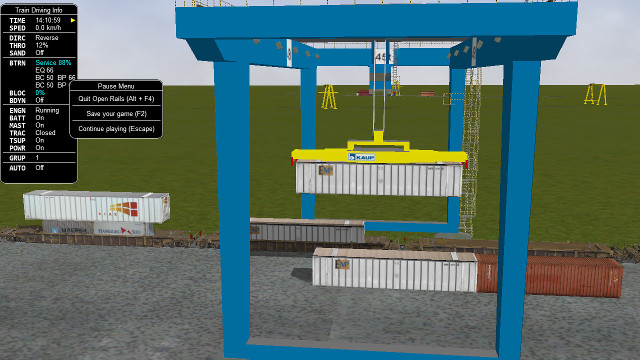
With this feature containers are not static objects laying on earth or on wagons, but may be loaded from a container station onto a wagon, or unloaded from a wagon and laid on a container station. The load/unload operations are performed through a crane, which is the heart of the container station.
The other component of the container station is the set of stack locations, that is the locations where containers may lay. Containers of same length can be stacked one above the other.
Wagons may be empty at game start, or partially or totally pre-loaded with containers, by
inserting the related data either in the consist (.con) file or in the .wag files.
Also container stations may be empty at game start, or partially or totally populated with
containers, inserting the related data in the activity (.act) file.
The loading and unloading operations are started by the player, by pressing the key <T>
for loading, and the key <Shift-T> . The operation is performed on the first wagon
(starting from the locomotive) which is within the container crane displacement range and which
fulfills the
required conditions (e.g. loading space available for loading, container present for unloading).
Double stack wagons are managed.
From a point of view of internal code structure, Open Rails handles container stations as special pickups.
9.5.2. How to define container data
Container shape files (.s) must be located in subfolders (or sub-subfolders) of the
Trainset folder.
Containers that can be managed must be provided with a Json .load-or file. The .load-or files
must be located in a subfolder of the Trainset folder. It is warmly advised to keep all
.load-or file in a single folder: Common.ContainerData is suggested. It is also advised to name
the .load-or files in a consistent way: 40HCtriton.load-or is suggested, where 40HC is the
container type and triton the brand painted on the container.
9.5.2.1. Format of the .load-or file
Here below a sample of a .load-or file:
{
      "Container":
      {
              "Name" : "triton",
              "Shape" : "COMMON_Container_3d\\Cont_40ftHC\\container-40ftHC_Triton.s",
              "ContainerType" : "C40ftHC",
              "IntrinsicShapeOffset": [0,1.175,0],
              "EmptyMassKG": 2100.,
                "MaxMassWhenLoadedKG": 28000.,
        }
}
“Container” is a fixed keyword.
“Name” has as value a string used by Open Rails when the container must be indentified in a message to the player.
“Shape” has as value the path of the container shape, having
Trainsetas base.“ContainerType” identifies the container type, which may be one of the following ones:
* C20ft
* C40ft
* C40ftHC
* C45ft
* C45ftHC
* C48ft
* C53ft
C48ft and C53ft have a HC height (2.90m)
“IntrinsicShapeOffset” has as value the offset in meters of the center of the bottom rectangle of the container with respect to the container shape file coordinates. Unfortunately often such offset is not [0,0,0], which would be advisable for newly produced containers. A simple way to state such offset is to use the
Show Bounding InfoofShape Viewer.“EmptyMassKG” is an optional parameter that defines the tare (weight when empty) of the container. If the parameter is not present, OR uses a default parameter, specific for that ContainerType.
“MaxMassWhenLoadedKG” is an optional parameter that defines the sum of the tare plus the maximum allowed payload. As above, if the parameter is not present, OR uses a default parameter, specific for that ContainerType.
9.5.3. Pre-setting a .wag file to accommodate containers
As a minimum following block must be present in the .wag file for a double stacker:
ORTSFreightAnims (
              WagonEmptyWeight ( 12.575t )
              LoadingAreaLength ( 12.20 )
              AboveLoadingAreaLength ( 12.20 )
              DoubleStacker ()
              Offset( 0 0.34 0 )
              IntakePoint ( 0 6.0 Container)
              )
WagonEmptyWeight is the weight of the wagon, when it has neither containers nor other weighing freight animations on board
LoadingAreaLength is the length in meters of the loading area available for containers
AboveLoadingAreaLength is the length in meters of the above loading area available for containers (parameter not needed if not double stacker)
DoubleStacker must be present if the wagon allows double stacking
Offset is the offset of the center of the rectangle of the loading area with respect to the shape file of the wagon.
The first and the third IntakePoint parameters have the same meanings than the ones used for generic pickups. The first parameter must be equal to the Z value of the offset.
Containeris mandatory.
This ORTSFreightAnims block can include also static freight animations as described in
the related paragraph.
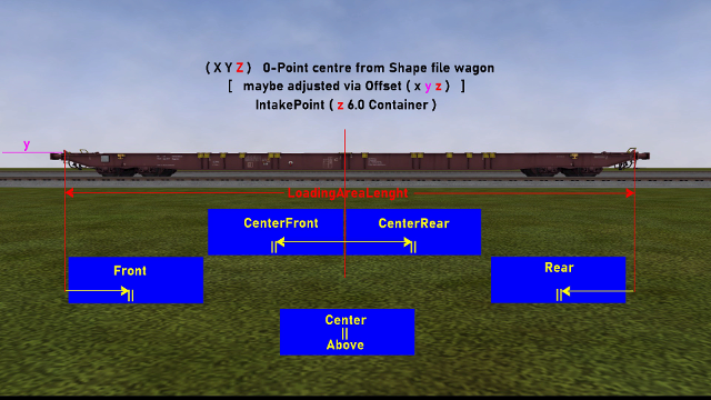
9.5.4. Allocation of the containers on the wagons
A container may have following positions within the loading area of the wagon: Rear, CenterRear, Center, CenterFront, Front and Above. Following picture shows where the first five positions are located on the wagon, while Above is the above position in dual-stack configurations. The Above position is always centered.
Some loading configurations are shown in following picture:
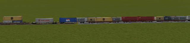
From left to right the loading configurations are present (locomotive on the left):
CenterFront, CenterRear, Above
Center
Front, Rear
Front, Center, Rear
Front, Rear
Front, CenterFront, CenterRear, Rear.
The real rules to allocate double-stacked containers must be respected:
no 20ft stacked above
only one container above
at least 40ft of containers below.
9.5.5. How to allocate containers on wagons at start of game
The containers may be allocated either by editing the .con file,
or by editing the .wag file, or in a mixed mode (some wagons in one mode,
some others in another mode).
9.5.5.1. Allocation through .con file
This allocation mode is the recommended one, as it is more flexible and provides easier visibility.
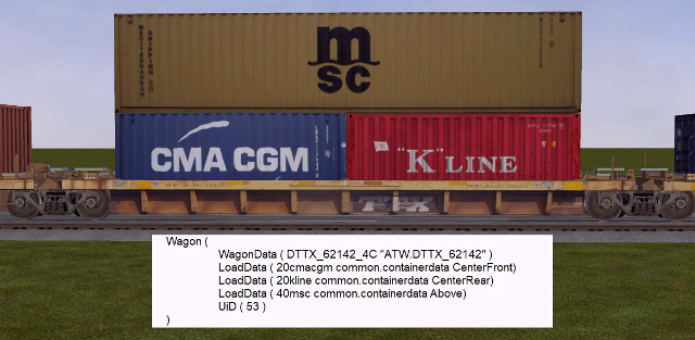
A wagon entry complete with the data about the containers loaded at startup is shown here:
Wagon (
          WagonData ( DTTX_620040_A ATW.DTTX_620040 )
          LoadData ( 20cmacgm common.containerdata CenterFront Empty)
          LoadData ( 20hamburgsud common.containerdata CenterRear Loaded)
          LoadData ( 40msc common.containerdata Above Random)
          UiD ( 11 )
)
As can be seen, for each container loaded at startup a LoadData entry must be
present. The meaning of the parameters is as follows:
The first parameter is the name of the
.load-orfileThe second parameter is the path (having
Trainsetas base path) where the.load-orfile residesThe third parameter indicates where the container is allocated on the wagon
The fourth parameter, which is optional, defines the load state of the related container, which is used to derive the weight of the container. If
Emptyis present, the weight of the empty container is used as actual weight; ifLoadedis present, the maximum weight (tare + payload) of the container is used; ifRandomis present, the weight is computed as follows: a random number between 0 and 100 is generated. If the number is below 31, the container is considered empty; else the number is used as percentage of the maximum weight of the container (tare + payload). The weight of the containers are added to the empty weight of the wagon, to compute the total weight of the wagon. If the parameter is not present, theRandomvalue is assumed.
The entry for the container allocated Above must be the last one.
CenterFront and CenterRear entries must be entered after Front or Rear entries.
The advantage of this type of allocation is that, for a single .wag file
(in the example DTTX_620040_A.wag) more possible container configurations are
possible, sparing the time of creating many .wag files that differ only on the
containers loaded.
Here below a picture with a sample entry in the .con file:
9.5.5.2. Allocation through .wag file
Content creators might prefer to provide packs of pre-loaded wagons. Therefore
it is also possible to set in .wag file the containers to be loaded at startup.
A minimum FreightAnimations entry in a .wag file to have the same pre-loaded container
set as in the previous paragraph is as follows:
ORTSFreightAnims (
              WagonEmptyWeight ( 12.575t )
              LoadingAreaLength ( 14.6 )
              AboveLoadingAreaLength ( 16.15 )
              DoubleStacker ()
              Offset( 0 0.34 0 )
              IntakePoint ( 0 6.0 Container)
              LoadData ( 20cmacgm common.containerdata CenterFront Empty)
              LoadData ( 20hamburgsud common.containerdata CenterRear Loaded)
              LoadData ( 40msc common.containerdata Above Random)
            )
As can be seen, the syntax of the LoadData entries is the same as in the case of
the .con file. Also here the fourth parameter is optional.
Obviously, using .wag files for this type of info, a different .wag file must
be created for every desired pre-loaded set of containers.
A single .con file can include Wagon entries for both types of allocation definition.
9.5.6. Container Station
The Container Station is composed by a container crane and a container stack area.
To insert a Container Station in a route, its object must be present in the .ref file as a
Pickup object. A .ref file entry sample is as follows:
Pickup (
  Class                   ( "Animated loader" )
  Filename                ( RMG_45.s )
  PickupType              ( _FUEL_COAL_ )
  Description             ( "Animated container crane" )
)
PickupType is set to _FUEL_COAL, but this will be overwritten by the data inserted in the
extension .w file (see here) within the Openrails
sufolder of the World folder.
Such extension .w file is formed by a general part, a container crane related part, and a
stack locations related part, as per following example (parts separated by blank lines)
SIMISA@@@@@@@@@@JINX0w0t______

Tr_Worldfile (
              Pickup (
                      UiD ( 21 )
                      PickupType ( 15 1 )

                      ORTSPickingSurfaceYOffset ( 2.25 )
                      ORTSPickingSurfaceRelativeTopStartPosition ( 0 6.75 0 )
                      ORTSGrabberArmsParts ( 2 )
                      ORTSCraneSound ( "ContainerCrane.sms" )

                      ORTSMaxStackedContainers ( 2 )
                      ORTSStackLocationsLength ( 12.19 )
                      ORTSStackLocations ( 12
                              StackLocation (
                                      Position ( -10 0 26 )
                                      Length ( 16.15 )
                                      )
                              StackLocation (
                                      Position ( -10 0 26 )
                                      MaxStackedContainers ( 1 )
                                      Flipped ( 1 )
                                      )
                              StackLocation (
                                      Position ( -10 0 0 )
                                      MaxStackedContainers ( 2 )
                                      )
                              StackLocation (
                                      Position ( -10 0 0 )
                                      Flipped ( 1 )
                                      )
                              StackLocation (
                                      Position ( -10 0 -26 )
                                      )
                              StackLocation (
                                      Position ( -10 0 -26 )
                                      Flipped ( 1 )
                                      Length ( 16.15 )
                                      )
                              StackLocation (
                                      Position ( -7 0 26 )
                                      Length ( 16.15 )
                                      )
                              StackLocation (
                                      Position ( -7 0 26 )
                                      Flipped ( 1 )
                                      )
                              StackLocation (
                                      Position ( -7 0 0 )
                                      )
                              StackLocation (
                                      Position ( -7 0 0 )
                                      Flipped ( 1 )
                                      )
                              StackLocation (
                                      Position ( -7 0 -26 )
                                      )
                              StackLocation (
                                      Position ( -7 0 -26 )
                                      Flipped ( 1 )
                                      Length ( 16.15 )
                                      )
                              )
              )
)
The UiD number must correspond to the uiD number that the pickup has in the main
.wfile.PickupType ( 15 1 ) identifies this pickup as being a container station.
More than a Pickup() block can be present in such extension file, one for every container station present in the route.
The container crane and stack location related data are described at a convenient point below.
9.5.6.1. Container Station (including container crane) shape file developing rules
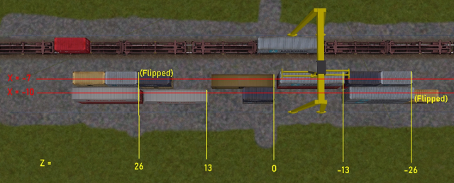
The shape file must have its Z Axis aligned with the track where the wagons to be loaded or unloaded stay.
The Z-zero of the shape file must be in the middle of the segment that the crane can cover in its motion (e.g. the crane Z-span could be -30 meters to 30 meters).
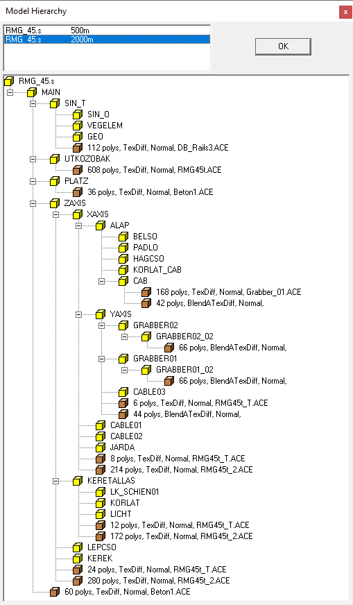
The animation of the part of the crane moving along the Z axis must be called
ZAXIS.The animation of the part of the crane moving transversally along the X axis must be called
XAXIS, and must be hierarchically dependent fromZAXIS.The animation of the part of the crane moving vertically along the Y axis must be called
YAXIS, and must be hierarchically dependent fromXAXIS.The grabbers are the extensible arms that pick the container. In the simplest case there are two sections, one extending towards positive Z for longer containers, and one extending towards negative Z. The first one must be called
GRABBER01and the second oneGRABBER02. Both must be hierarchically dependent fromYAXIS. In the most complex case each of the two “arms” is composed by two parts, which move like a telescope. Such second couple of arms must be calledGRABBER01_O2andGRABBER02_02. They must be hierarchically dependent fromGRABBER01andGRABBER02. The spans ofGRABBER01andGRABBER02must be symmetric, and the same applies for the other couple of spans. Moreover the spans ofGRABBER01andGRABBER01_02must be equal (and symmetrically also the other couple).The names of the cable parts that have a partially autonomous motion along the Y axis (to simulate cable winding and unwinding) must start with
CABLEand must be hierarchically dependent fromYAXIS.
The following diagram, taken from Shape Viewer, sums up the above rules.
Following are the significant animation entries of a crane’s shape file:
animations ( 1
              animation ( 2 30
                      anim_nodes ( 30
                              anim_node MAIN (
                                      controllers ( 0 )
                              )
              ...
                              anim_node ZAXIS (
                                      controllers ( 1
                                              linear_pos ( 3
                                                      linear_key ( 0 0 0 -139.5 )
                                                      linear_key ( 12 0 0 139.5 )
                                                      linear_key ( 24 0 0 -139.5 )
                                              )
                                      )
                              )
                              anim_node XAXIS (
                                      controllers ( 1
                                              linear_pos ( 3
                                                      linear_key ( 0 0 0 0 )
                                                      linear_key ( 3 26.4 0 0 )
                                                      linear_key ( 6 0 0 0 )
                                              )
                                      )
                              )
              ...
                              anim_node YAXIS (
                                      controllers ( 1
                                              linear_pos ( 3
                                                      linear_key ( 0 0 11.7 0 )
                                                      linear_key ( 2 0 0 0 )
                                                      linear_key ( 4 0 11.7 0 )
                                              )
                                      )
                              )
                              anim_node GRABBER02 (
                                      controllers ( 1
                                              linear_pos ( 3
                                                      linear_key ( 0 0 0 -2.515 )
                                                      linear_key ( 1 0 0 0 )
                                                      linear_key ( 2 0 0 -2.515 )
                                              )
                                      )
                              )
                              anim_node GRABBER02_02 (
                                      controllers ( 1
                                              linear_pos ( 3
                                                      linear_key ( 0 0 0 -2.513 )
                                                      linear_key ( 1 0 0 0 )
                                                      linear_key ( 2 0 0 -2.513 )
                                              )
                                      )
                              )
                              anim_node GRABBER01 (
                                      controllers ( 1
                                              linear_pos ( 3
                                                      linear_key ( 0 0 0 2.515 )
                                                      linear_key ( 1 0 0 0 )
                                                      linear_key ( 2 0 0 2.515 )
                                              )
                                      )
                              )
                              anim_node GRABBER01_02 (
                                      controllers ( 1
                                              linear_pos ( 3
                                                      linear_key ( 0 0 0 2.513 )
                                                      linear_key ( 1 0 0 0 )
                                                      linear_key ( 2 0 0 2.513 )
                                              )
                                      )
                              )
              ...
                              anim_node CABLE02 (
                                      controllers ( 1
                                              linear_pos ( 3
                                                      linear_key ( 0 0 22.32 0 )
                                                      linear_key ( 1 0 15.72 0 )
                                                      linear_key ( 2 0 22.32 0 )
                                              )
                                      )
                              )
                              ...
                      )
              )
      )
It can be noted that the frame count is different for different animation nodes, e.g. the ZAXIS has 0, 12, 24. This permits to scale down the motion speed along that axis to a realistic value.
9.5.6.3. Stack Locations
Within the area that can be reached by the container crane (rails area apart)
stack locations where the containers can be laid down can be defined in the extension
.w file.
The stack locations are defined by following parameters:
Position: the coordinates of the center point of one of the short sides of the stack location; if noFlipped ( 1 )line is present, the location area extends towards the increasing Z axis; if instead such line is present, the location area extends towards the decreasing Z axis. If two stack locations have the same position, and one is flipped and the other isn’t, the containers will be laid back-to-back, optimizing space used.Length: the maximum length of the containers that can be laid down on that stack locationMaxStackedContainers: The maximum number of containers that can be stacked one above the other on that stack location
The Length and MaxStackedContainers parameters are optional and, when present, override
the default values present in the ORTSStackLocationsLength and ORTSMaxStackedContainers.
If ORTSStackLocationsLength is greater or equal to 12.20m, which is twice the length of
a 20ft container, Open Rails applies a space optimization strategy: for each stack location
(let’s call it the mother stack location), another one (let’s call it the child stack location)
is created on a position with a Z value which is 6.095m greater than the mother
stack location (if the latter is flipped the Z value is 6.095m smaller). This child stack location
can be occupied by a 20ft container only, and only if the mother stack location is empty or
occupied by a 20ft container too. The child stack location has an index which is equal to
the mother stack location index plus the total number of mother stack locations. Once both
the mother and the child stack locations are empty, the mother stack location is again available
for any type of container of suitable length.
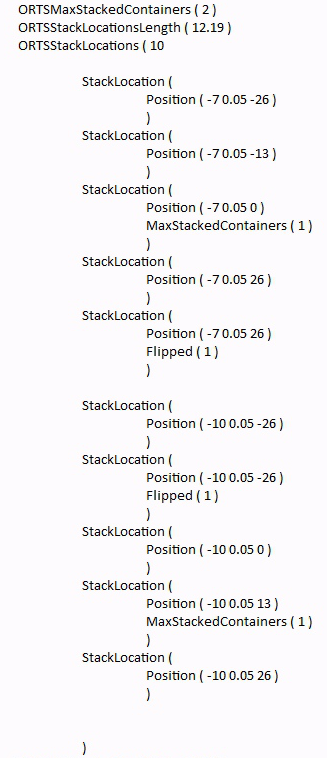
A further example of a stack locations allocation code and of its physical counterpart in the container station follows. It can be noted that stack location 0 has a 20ft container on it, and so has its child stack location 10. Same applies to stack location 3 and its child stack location 13.
9.5.6.4. Population of container stations at game start
Container stations may be populated at game start. This occurs by inserting a .load-stations-loads-or
file in the Openrails subfolder of the “Activities” folder of the
route, and inserting the following line at the bottom of the Tr_Activity_Header in
.act files
ORTSLoadStationsPopulation ( BigContainerStationPopulation )
where BigContainerStationPopulation is the name of the .load-stations-loads-or file. At the moment population at
game start is possible only in Activity mode.
The .load-stations-loads-or file is a Json file. An example is shown here below
      "ContainerStationsPopulation": [
              {
                      "LoadStationID" : { "wfile" : "w-005354+014849.w", "UiD" :  21, },
                      "LoadData" : [
                              { "File" : "40HCcai", "Folder" : "common.containerdata", "StackLocation" : 0, "LoadState" : "Empty"},
                              { "File" : "40HCcai", "Folder" : "common.containerdata", "StackLocation" : 0, "LoadState" : "Loaded"},
                              { "File" : "20cmacgm", "Folder" : "common.containerdata", "StackLocation" : 2, "LoadState" : "Random"},
                              { "File" : "20kline", "Folder" : "common.containerdata", "StackLocation" : 2, },
                              { "File" : "45HCtriton", "Folder" : "common.containerdata", "StackLocation" : 5, },
                              { "File" : "45HCtriton", "Folder" : "common.containerdata", "StackLocation" : 5, },
                              { "File" : "48emp", "Folder" : "common.containerdata", "StackLocation" : 6, },
                              { "File" : "20maersk", "Folder" : "common.containerdata", "StackLocation" : 14, },
                              { "File" : "20maersk3", "Folder" : "common.containerdata", "StackLocation" : 14, },
                      ]
              },
              {
                      "LoadStationID" : { "wfile" : "w-005354+014849.w", "UiD" :  210, },
                      "LoadData" : [
                      ...
                      ]
              },
              ...
      ]
}
The file can define the population at startup of many container stations.
The
LoadStationIDcontains the info needed to identify the container station.The
LoadDataarray contains the data to populate the container station.The value of
Fileis the name of the.load-orfile identifying the container.The value of
Folderis the path where the.load-orcan be found, starting from theTRAINSET.The value of
StackLocationis the index of the Stack Location. If the index is equal or higher than the number of stack locations defined in the extension.wfile, the index refers to a child stack location.If more than a container is defined for a stack location, they are stacked one above the other.
The
LoadStateparameter is optional, and has the same meaning and values as the parameter of the same name which can be present in .con or .wag files.
The container station population file must be written taking into account the constraints of the stack locations (container length must be smaller than stack location lenght, stacked containers can’t exceed the allowed number, a stack location must contain containers of same length).
9.6. Multiple passenger viewpoints
Additional passenger viewpoints may be added within a carriage or locomotive that is provided with passenger viewpoint.
Such additional passenger viewpoints may be defined within an include file with the format shown in following example for the legacy oebarcar.wag (located in the 380 folder) MSTS wagon:
include ( ../oebarcar.wag )

Wagon (
      ORTSAlternatePassengerViewPoints (
              ORTSAlternatePassengerViewPoint (
                      PassengerCabinHeadPos ( -0.0 2.85801 -6.091 )
                      RotationLimit ( 50 270 0 )
                      StartDirection ( 0 0 0 )
              )
              ORTSAlternatePassengerViewPoint (
                      PassengerCabinHeadPos ( -0.5 2.35801 -1.791 )
                      RotationLimit ( 50 270 0 )
                      StartDirection ( 0 0 0 )
              )
              ORTSAlternatePassengerViewPoint (
                      PassengerCabinHeadPos ( 0.9 2.35801 -1.791 )
                      RotationLimit ( 50 270 0 )
                      StartDirection ( -5 -90 0 )
              )
      )
)
If the passenger viewpoints are defined in the base .wag or .eng file, they must be defined below the Inside () block.
At runtime, when in passenger view, the player may pass from one viewpoint to the other by pressing Shift-5.
9.7. Bell animation
Open Rails supports bell animation. The bell animation matrix must be named ORTSBELL within the engine’s .s file. Its default frame rate is 8 frames per second. The default frame rate may be modified through the optional parameter ESD_ORTSBellAnimationFPS (n), to be inserted within the .sd file related to the .s file. n defines the animation FPS. It is advisable that the related sound stream within the .sms file is synchronized with the visible animation. To accomplish this the .wav file should contain two bell strokes, which time interval is equal to the time interval of a bell swing from an oscillation end point to the opposite end point. As the first bell stroke should not start immediately, but when the bell is about at the maximum of the swing, the first stroke within the .wav file should be at the time distance equivalent to the oscillation from center point to an oscillation end point. The file should have one cue point at its beginning and one after the time interval of a complete bell swing forward and backward, and should have a final fadeoff for best result.
9.8. Brake Equipment Animations
Open Rails now supports animation of brake rigging components driven by the brake system simulation.
9.8.1. Brake Cylinder Animation
On engines and wagons with advanced brake cylinder parameters ORTSBrakeCylinderDiameter and ORTSBrakeCylinderPistonTravel defined, Open Rails will simulate the motion of the brake cylinders and brake rigging. This simulation can be used to drive animations of brake cylinders using animation matricies with names that start with ORTSBRAKECYLINDER. This animation type should NOT be used for any brake equipment that can be actuated by the brake cylinder and the handbrakes. See the section on brake rigging animation for details.
Unlike other animation types, the keyframes for brake cylinders do not represent time, and cannot be set to arbitrary values. Instead, the key value represents the level of brake cylinder extension. A keyframe value of 8 represents the state where the brake cylinder has taken up the slack in the brake rigging, 10 represents the level of brake cylinder extension at 50 psi/3.5 bar, and the maximum value of cylinder extension is 16, which should not be possible in normal operation. These values are the same regardless of the settings used in the engine or wagon file. NOTE: Brake animations should at minimum have 2 animation frames, one at keyframe 0 and the second at keyframe 8. Other keyframes are optional and may be included to fine-tune the animation.
Note that the advanced brake cylinder calculations are only run on air brake systems on the player train to save computing power. As such, brake cylinder animations on AI trains or brake systems other than air brakes behave in a simplified manner.
9.8.2. Handbrake Animation
Handbrake wheels and levers can also be animated using the same process as two-state animations such as mirrors, and the keyframe values will represent time in seconds like other animations. The matrix name for animated handbrakes must begin with ORTSHANDBRAKE.
9.8.3. Brake Rigging and Brake Shoe Animation
For any brake equipment that is actuated by both the handbrake and the brake cylinders (typically, this includes brake rigging and brake shoes, but sometimes also includes brake cylinders themselves), use animations with a matrix name starting with ORTSBRAKERIGGING. For this type of animation, the animation state will respond to the brake cylinder travel or the handbrake, whichever input is greater.
The same keyframe rules as brake cylinder animations apply here. A key value of 8 should represent the state where the brake shoes have made contact with the friction surface, and no further motion of brake shoes should occur after 8, though the brake levers may still animate beyond this point. Applying the handbrake will also drive the animation to keyframe 10 (ie: same as 50 psi/3.5 bar application).
9.9. Coupler and Airhose Animation
Open Rails supports animation of couplers and air hoses. Coupler animation will move the couplers and air hoses as the train moves and the coupler slack increases or decreases. Couplers will also rotate as the train travels around a curve.
To implement this separate models need to be provided for the couplers and air hoses. A separate model for the coupled and uncoupled state is suggested.
To enable coupler animation the following parameters need to be included in the coupler code section of the WAG file:
FrontCouplerAnim - Coupler shape to be displayed at the front of the car when it is coupled.
FrontCouplerOpenAnim - Coupler shape to be displayed at the front of the car when it is uncoupled.
RearCouplerAnim - Coupler shape to be displayed at the rear of the car when it is coupled.
RearCouplerOpenAnim - Coupler shape to be displayed at the rear of the car when it is uncoupled
All four of the above will have the following format:
CouplerAnimation ( couplershape.s, x, y, z ) where the coupler shape file name is included along with x, y, z values that offset the coupler in the three axis.
For the airhose animation the following parameters must be included in the coupler code section of the WAG file:
FrontAirHoseAnim - Air hose shape to be displayed at the front of the car when it is coupled.
FrontAirHoseDisconnectedAnim - Air hose shape to be displayed at the front of the car when it is uncoupled.
RearAirHoseAnim - Air hose shape to be displayed at the rear of the car when it is coupled.
RearAirHoseDisconnectedAnim - Air hose shape to be displayed at the rear of the car when it is uncoupled.
Each of these parameters will have the same format as indicated above for the coupler shapes.
Open rails uses some defaults to calculate the required movement and angles for coupler and air hose
shape movement, however for greater accuracy the modeler can add specific values such as
ORTSLengthAirHose. In addition the length values suggested in the Derailment Coefficient should
also be added.
9.10. Passenger doors
Passenger doors are opened and closed (by default) using the <Q> and <Shift+Q> keys.
It is possible to add opening and closing delays, which can be useful to delay the indication of
“Doors closed” until all doors are fully closed.
The delays can be added inserting the following block in the wagon section of any
ENG or WAG file:
ORTSDoors (
  ClosingDelay ( 5s )
  OpeningDelay ( 1s )
)
9.11. Trainset windows
Left and right 2D- or 3D-cab windows can be animated, showing the animation both in cabview and in external views. For locomotives also two windows for the rear cab can be defined.
The external sounds and the track sound are reproduced unattenuated with open window. To have a volume difference, two lines as follows must be added to the wagon section of the .eng or .wag file:
ORTSExternalSoundPassedThroughPercent ( 30 )
ORTSTrackSoundPassedThroughPercent ( 25 )
Numbers in parenthesis may vary from 0 (no sound heard internally) to 100 (sound heard unattenuated). Note that, if these two lines aren’t added, but audio option “% of external sound heard internally” is set to a value lower than 100, the above effect will be still available with external sounds, but not with the track sound.
Keyboard commands to toggle window state are listed here .
Names of the animations are as follows.
Names for the windows animations as seen from the external camera views (the ones to be inserted in the .s file of the trainset) must start with following strings:
LEFTWINDOWFRONT
RIGHTWINDOWFRONT
LEFTWINDOWREAR
RIGHTWINDOWREAR
In case of carriages, only the first two apply.
Names for the windows animations as seen from within a 2D cab (same names are valid for front and rear cab); left and right are considered as seen from the related cab:
ORTS_2DEXTERNALLEFTWINDOW
ORTS_2DEXTERNALRIGHTTWINDOW
Note that in general the lateral windows will be located in the side views of the 2D cab. Therefore the related control blocks in the .cvf file will have to be located as described here .
Names for the window animations as seen from within a 3D cab (the ones to be inserted in the .s file of the 3D cab); Left and right are considered as seen in the forward direction of the first cab. The convention difference between 2D and 3D cabs is due to the difference in the handling of the cabs. NOTE: these 4 controls are not needed in the .cvf file (same applies also for wipers, doors and so on as seen from within a 3D cab):
ORTS_EXTERNALLEFTWINDOWFRONT
ORTS_EXTERNALRIGHTWINDOWFRONT
ORTS_EXTERNALLEFTWINDOWREAR
ORTS_EXTERNALRIGHTWINDOWREAR
ORTS_LEFTWINDOW and ORTS_RIGHTWINDOW are the names of the controls that can be inserted in the .cvf file and in the 3Dcab .s file to command the state change with the mouse.
Here is an example of the animation of the left window in a 2D cab:
ORTSCabViewControls
( 1
                ORTSAnimatedDisplay  (
                Type ( ORTS_2DEXTERNALLEFTWINDOW MULTI_STATE_DISPLAY )
                Position ( 101 69 235 365 )
                Graphic ( ../../Common.Cab/CabE464/FinestraSX.ace )
                ORTSCycleTime ( 0.6 )
                        States ( 16 4 4
                        State (
                                Style ( 0 )
                                SwitchVal ( 0 )
                        )
                        State (
                                Style ( 0 )
                                SwitchVal ( 0.0625 )
                        )
                        State (
                                Style ( 0 )
                                SwitchVal ( 0.125 )
                        )
                        State (
                                Style ( 0 )
                                SwitchVal ( 0.1875 )
                        )
                        State (
                                Style ( 0 )
                                SwitchVal ( 0.25 )
                        )
                        State (
                                Style ( 0 )
                                SwitchVal ( 0.3125 )
                        )
                        State (
                                Style ( 0 )
                                SwitchVal ( 0.375 )
                        )
                        State (
                                Style ( 0 )
                                SwitchVal ( 0.4375 )
                        )
                        State (
                                Style ( 0 )
                                SwitchVal ( 0.5 )
                        )
                        State (
                                Style ( 0 )
                                SwitchVal ( 0.5625 )
                        )
                        State (
                                Style ( 0 )
                                SwitchVal ( 0.625 )
                        )
                        State (
                                Style ( 0 )
                                SwitchVal ( 0.6875 )
                        )
                        State (
                                Style ( 0 )
                                SwitchVal ( 0.75 )
                        )
                        State (
                                Style ( 0 )
                                SwitchVal ( 0.825 )
                        )
                        State (
                                Style ( 0 )
                                SwitchVal ( 0.88 )
                        )
                        State (
                                Style ( 0 )
                                SwitchVal ( 0.94 )
                        )
                )
                ORTSCabviewpoint ( 1 )
        )
)
FinestraSX.ace contains the various frames, from window fully close to window fully open. ORTSCycleTime means that the opening/closing time of the window is 0.6 seconds. If one wants to use higher times, more frames are needed to get a smooth animation. Note that, as explained above, the control is within the ORTSCabviewControls block, which is skipped by MSTS and older OR versions to avoid error messages, and note that the ORTSCabviewpoint ( 1 ) line specifies that that animation is in the left cabview.
A simple control block to move a window by clicking the mouse can be as follows:
TwoState (
                Type ( ORTS_LEFTWINDOW TWO_STATE )
                Position ( 120 425 30 21 )
                Graphic ( cab.ace )
                NumFrames ( 2 2 1 )
                Style ( ONOFF )
                MouseControl ( 1 )
                )
If there is no specific window control in the real cab, you can locate this control on the window itself, using a transparent graphic. So, clicking on the window, you change its state. This can be applied both to 2D and 3D cabs.
Sound triggers for windows animation are listed here .
9.11.1. Specifics for carriage window animations
One window to the left and one window to the right of the carriage may be animated. They can be opened and closed only via keyboard (Ctrl-Q for left window and Ctrl-Shift-Q for right window, as for locomotives).
Note that the carriage must have only the main shape file (no passenger view shape file). This main shape file can include also the inside structure of the carriage; note that when a .wag or .eng file has an Inside block defined, and such block doesn’t include a line specifying the .s file, OR will use the main shape file to display the inside. So such shape file will display the window animation both with the passenger camera (inside view) and with the external cameras (outside views).
9.12. C# engine scripting
To simulate especially complex behavior, Open Rails provides a C# scripting interface for a number of systems on the player locomotive. Like the Open Rails program itself, these scripts are written in .cs files containing C# classes, but they are compiled and linked at runtime, so they don’t depend on changes in the core program itself and can be distributed with rolling stock content. Scripts will run if referenced by OR-specific fields in the .eng file.
System |
C# class |
.eng block |
|---|---|---|
Train brake controller |
|
|
Engine brake controller |
|
|
Circuit breaker |
|
|
Traction cut-off relay |
|
|
Diesel power supply |
|
|
Electric power supply |
|
|
Passenger car power supply |
|
|
Pantograph selector |
|
|
Voltage selector |
|
|
Power limitation selector |
|
|
Train Control System |
|
|
Scripts reside in a Script subfolder within the engine’s folder and must
contain a class named after the script’s own filename. For example, if the
script’s filename is AmtrakTCS.cs, OR will search for a single class named
AmtrakTCS. (It is also possible to place the script in another location,
such as a Common.Script folder in the TRAINSET folder, by prepending the
appropriate amount of parent directory tokens ..\ relative to the engine’s
Script folder.) The script’s code runs on the UpdaterProcess thread. This
example, which would need to be placed in a file named DemoTCS.cs,
illustrates the minimum code required for a Train Control System script:
using System;
using ORTS.Scripting.Api;

namespace ORTS.Scripting.Script
{
    class DemoTCS : TrainControlSystem
    {
        public override void HandleEvent(TCSEvent evt, string message) {}
        public override void Initialize()
        {
            Console.WriteLine("TCS activated!");
        }
        public override void SetEmergency(bool emergency) {}
        public override void Update() {}
    }
}
Observe that the script’s class must reside in the ORTS.Scripting.Script
namespace and that it subclasses the abstract class of the desired system. It
also references external assemblies with using directives. OR makes the
following .NET assemblies available to scripts:
System
System.Core
ORTS.Common
Orts.Simulation
Scripts communicate with the simulator by invoking methods in the base class.
For example, this script might invoke the TrainLengthM() method of the
TrainControlSystem class, which returns the length of the player train. More
methods are available in the ORTS.Scripting.Api.AbstractScriptClass class,
which TrainControlSystem is itself a subclass of.
Finally, if a script contains a syntax or typing error, OR will log an exception during the loading process and run the simulation without it.
9.12.1. Developing scripts with Visual Studio
While it is certainly possible to develop scripts with a plain text editor, the code completion and debugging aids available in an IDE like Visual Studio make for a vastly more comfortable programming experience. If you have a development environment set up to build Open Rails, you can use Visual Studio to edit your scripts with these creature comforts. What follows is a suggested workflow:
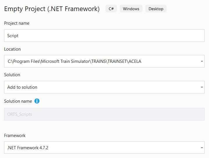
First, in your copy of the OR source code, make a copy of your
Source\ORTS.slnfile. Keep it in theSource\folder, but give it a novel name likeORTS_Scripts.sln. (You could also modify the original ORTS solution, but then you’d have to remember not to check it in to source control.) Add a new project to the solution and select the empty .NET project.In the configuration dialog, set the new project to be added to the existing solution, set its location to be the folder of the engine you’re scripting, and set its name to “Script”. (For now, you must use “Script”, but you can rename the project after it’s created.) You can leave the .NET framework version set to its default. Then, create the project.
The new project folder becomes the very
Scriptsubfolder that OR will search for scripts. Add references to the ORTS.Common and Orts.Simulation assemblies, which will enable IntelliSense features inside your editor when you edit scripts. You may now rename the project as you like (which will not rename the folder) and delete the pregenerated App.config file.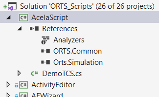
Finally, open the Build Configuration Manager and set the new script project not to build for both the Debug and Release configurations.

With this setup, Visual Studio will type-check your scripts and make suggestions when you use the Open Rails API. You can also set breakpoints within your script, which will be caught by RunActivity.exe if run inside Visual Studio.
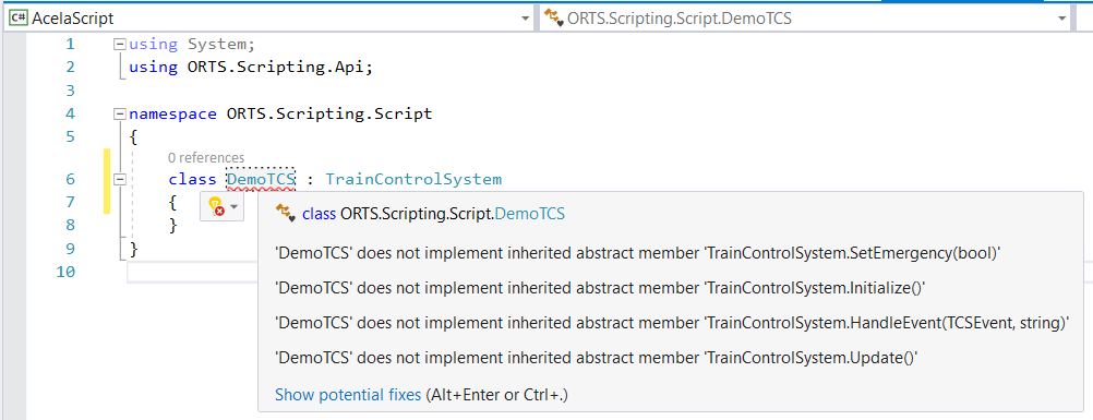
Note that Visual Studio uses relative paths, so if you ever move any folders, you’ll need to fix the references by hand.
9.12.2. Brake controller
The brake controller script customizes the behavior of the train’s brakes, allowing for much greater systems fidelity compared to what is possible with the model inherited from MSTS. For this purpose, the script can read the state of the brake controls and set the air pressures of the brake reservoirs.
Use the following .eng parameter to load a brake controller script:
Engine (
    ORTSTrainBrakeController ( "YourBrakes.cs" )
)
or:
Engine (
    ORTSEngineBrakeController ( "YourBrakes.cs" )
)
The .cs extension is optional. “MSTS” loads the default MSTS-compatible implementation, so do not use this name for your own script.
9.12.3. Circuit breaker
Available for electric locomotives only. The circuit breaker script controls the behavior of the locomotive’s circuit breaker.
Use the following .eng parameter to load a circuit breaker script:
Engine (
    ORTSCircuitBreaker ( "YourCB.cs" )
    ORTSCircuitBreakerClosingDelay ( 2s )
)
ORTSCircuitBreaker refers to the circuit breaker script in the engine’s Script
subfolder. For this field, the .cs extension is optional. Alternatively, there are several
built-in OR circuit breaker implementations:
“Automatic”: no driver intervention required, circuit breaker is closed when conditions are met.
“Manual”: a circuit breaker switch with open and closed positions.
“PushButtons”: a circuit breaker with dedicated open and close buttons.
“TwoStage”: circuit breaker closing is authorized by a switch. If the switch is off, the circuit breaker is kept open. Once the switch is activated, it is required to use a second button to order the closing.
Please do not use these names for your own script, since the generic implementation will be loaded instead.
ORTSCircuitBreakerClosingDelay refers to the delay between the closing command of the circuit breaker
and the effective closing of the circuit breaker.
9.12.4. Traction cut-off relay
Available for diesel locomotives only. The traction cut-off relay script controls the behavior of the locomotive’s traction cut-off relay.
Use the following .eng parameter to load a traction cut-off relay script:
Engine (
    ORTSTractionCutOffRelay ( "YourTCOR.cs" )
    ORTSTractionCutOffRelayClosingDelay ( 2s )
)
ORTSTractionCutOffRelay refers to the traction cut-off relay script in the engine’s Script
subfolder. For this field, the .cs extension is optional. Alternatively, there are several
built-in OR traction cut-off relay implementations:
“Automatic”: no driver intervention required, circuit breaker is closed when conditions are met.
“Manual”: a traction cut-off switch with open and closed positions.
“PushButtons”: a traction cut-off relay with dedicated open and close buttons.
Please do not use these names for your own script, since the generic implementation will be loaded instead.
ORTSTractionCutOffRelayClosingDelay refers to the delay between the closing command of the traction cut-off relay
and the effective closing of the relay.
9.12.5. Pantograph, voltage and power limitation selectors
Available for electric locomotives only. The scripts control the behavior of the locomotive’s pantograph selector, voltage selector and power limitation selector respectively.
Use the following .eng parameters to load power selector scripts:
Engine (
    ORTSPantographSelector (
      Script ( "YourPSScript.cs" )
      SelectorPositions ( ... )
    )
    ORTSVoltageSelector (
      Script ( "YourVSScript.cs" )
      SelectorPositions ( ... )
    )
    ORTSPowerLimitationSelector (
      Script ( "YourPLSScript.cs" )
      SelectorPositions ( ... )
    )
)
Script refers to the circuit breaker script in the engine’s Script
subfolder. For this field, the .cs extension is optional. Alternatively, there are several
built-in OR selector implementations which can be used if custom features such as interlocking
with other devices are not required:
“Default”: a selector with sequential positions.
“Circular”: same as above, but the first position follows again after the last one.
Please do not use these names for your own script, since the generic implementation will be loaded instead.
9.12.6. Diesel and electric power supply
Available for diesel and electric locomotives only. The power supply script determines whether or not the locomotive is serviceable (see also the description of the diesel power supply and the electric power supply) given the current line voltage, pantograph position, circuit breaker state, etc. It is also capable of forbidding some operations related to the power supply if some conditions are not met.
Use the following .eng parameter to load a power supply script:
Engine (
    ORTSPowerSupply ( "YourEPS.cs" )
    ORTSPowerSupplyParameters ( "YourEPS.ini" )
    ORTSPowerOnDelay ( 5s )
    ORTSAuxPowerOnDelay ( 10s )
)
ORTSPowerSupply refers to the power supply script in the engine’s Script
subfolder. For this field, the .cs extension is optional. “Default” will load the generic OR power supply
implementation, so do not use this name for your own script.
ORTSPowerSupplyParameters, an optional field, refers to an .ini file,
also in the Script subfolder, whose parameters will be made available to the
power supply script through the GetBoolParameter(), GetIntParameter(),
GetFloatParameter(), and GetStringParameter() methods. This .ini file provides for easy customization of
the behavior of the power supply script by end users.
ORTSPowerOnDelay refers to the delay between the closing of the circuit breaker or the traction cut-off relay
and the availability of the power for traction.
ORTSAuxPowerOnDelay refers to the delay between the closing of the circuit breaker or the traction cut-off relay
and the availability of the power for auxiliary systems.
9.12.7. Passenger car power supply
Available for passenger cars using electric heating. The power supply script determines whether or not the systems of the cars have power and calculates the power consumption on the Electric Train Supply.
If the locomotive is a diesel locomotive, the power consumed by the cars is no longer available for traction.
Use the following .wag parameter to load a power supply script:
Wagon (
    ORTSPowerSupply ( "YourEPS.cs" )
    ORTSPowerOnDelay ( 5s )
    ORTSPowerSupplyContinuousPower ( 500W )
    ORTSPowerSupplyHeatingPower ( 2kW )
    ORTSPowerSupplyAirConditioningPower ( 3kW )
    ORTSPowerSupplyAirConditioningYield ( 0.9 )
    ORTSHeatingCompartmentTemperatureSet ( 20degC )
)
ORTSPowerSupply refers to the power supply script in the wagon’s Script
subfolder. For this field, the .cs extension is optional. “Default” will load the generic OR power supply
implementation, so do not use this name for your own script.
ORTSPowerOnDelay refers to the delay between the availability of the power on the Electric Train Supply
cable and the availability of the power for the systems (for example, start-up of the static power converter).
ORTSPowerSupplyContinuousPower refers to the power which is consumed continuously (for example, battery chargers, lights, etc.).
ORTSPowerSupplyHeatingPower refers to the power which is consumed when the heating is active.
ORTSPowerSupplyAirConditioningPower refers to the power which is consumed when the air conditioning (cooling) is active.
ORTSPowerSupplyAirConditioningYield refers to the yield of the air conditioning (ratio of the heat flow rate
by the electric power of the air conditioning system).
ORTSHeatingCompartmentTemperatureSet refers to the desired temperature inside the car.
9.12.8. Train Control System
9.12.8.1. General
The Train Control System, or TCS, script is intended to model train safety and cab signalling systems. It can manipulate the locomotive’s controls and speed limit displays, impose penalty brake applications, read upcoming signal aspects and speed limits, and play warning sounds.
Use the following .eng parameters to load a TCS script:
Engine (
    ORTSTrainControlSystem ( "YourTCS.cs" )
    ORTSTrainControlSystemParameters ( "YourTCS.ini" )
    ORTSTrainControlSystemSound ( "YourTCSSounds.sms" )
)
ORTSTrainControlSystem refers to the TCS script in the engine’s Script
subfolder. For this field, the .cs extension is optional.
ORTSTrainControlSystemParameters, an optional field, refers to an .ini file,
also in the Script subfolder, whose parameters will be made available to the
TCS script through the GetBoolParameter(), GetIntParameter(),
GetFloatParameter(), and GetStringParameter() methods of the
TrainControlSystem class. This .ini file provides for easy customization of
the behavior of the TCS script by end users.
This is an excerpt from an .ini file:
[General]
AWSMonitor=true
EmergencyStopMonitor=false
VigilanceMonitor=true
OverspeedMonitor=false
DoesBrakeCutPower=true
BrakeCutsPowerAtBrakeCylinderPressureBar=
[AWS]
Inhibited=false
WarningTimerDelayS=3
BrakeImmediately=false
TrainStopBeforeRelease=false
ActivationOnSpeedLimitReduction=true
SpeedLimitReductionForActivationMpS=11.176
BeaconDistanceToPostM=1186
AppliesCutsPower=true
As can be seen, the .ini file is divided in subgroups. As an example, parameter [AWS]Inhibited would be read by following line of code in the script :
AWSInhibited = GetBoolParameter("AWS", "Inhibited", false);
where the final false is the default value, if the parameter can’t be found.
ORTSTrainControlSystemSound, an optional field, refers to a .sms file either
in the engine’s SOUND folder or in the global SOUND folder. If provided,
OR will load this sound library alongside the locomotive’s standard cab sounds.
The TCS script can play back sounds using any of the TriggerSound... methods
of the base class, which in turn activate the TCS-related
discrete triggers numbered from 109 through 118.
8 further generic discrete sound triggers are available, named GenericEvent1 to GenericEvent8 and accessible to the script by lines like following one:
SignalEvent(Event.GenericEvent1);
9.12.8.2. Access to the Simulation methods and variables
The abstract class for the TCS scripts provides a significant amount of methods to access variables of interest for the TCS: as an example:
public Func<int, Aspect> NextSignalAspect;
might be called within the script as follows:
var nextSignalAspect = NextSignalAspect(1);
which would return the aspect of the second normal signal in front of the player train.
However it is quite impossible to foresee all needs that a TCS script has and to provide a method for everyone of these needs. For this reason following method is available:
public Func<MSTSLocomotive> Locomotive;
which returns a handle for the player locomotive instance of the MSTSLocomotive class. Through such handle all public classes, methods and variables of the OR Simulation environment can be accessed within the script.
The Train Control System class provides the ETCSStatus field, which controls the information to be displayed in the ETCS DMI. For example, the following block orders the DMI to show the circular speed gauge in yellow colour as the train approaches a speed restriction:
ETCSStatus.CurrentMonitor = Monitor.TargetSpeed;
ETCSStatus.CurrentSupervisionStatus = SupervisionStatus.Indication;
ETCSStatus.TargetDistanceM = 1234.5f;
ETCSStatus.AllowedSpeedMpS = 50;
ETCSStatus.InterventionSpeedMpS = 52.5f;
ETCSStatus.TargetSpeedMpS = 25;
9.12.8.3. Emergency braking triggered by the simulator
The emergency brakings triggered by the simulator are always sent to the TCS script.
Two functions are used to transmit this information:
public override void HandleEvent(TCSEvent evt, string message)
The events sent are EmergencyBrakingRequestedBySimulator, EmergencyBrakingReleasedBySimulator and ManualResetOutOfControlMode.
For the first event, the reason of the emergency braking is also sent:
SPAD: The train has passed a signal at danger at the front of the trainSPAD_REAR: The train has passed a signal at danger at the rear of the trainMISALIGNED_SWITCH: The train has trailed a misaligned switchOUT_OF_AUTHORITY: The train has passed the limit of authorityOUT_OF_PATH: The train has ran off its allocated pathSLIPPED_INTO_PATH: The train has slipped back into the path of another trainSLIPPED_TO_ENDOFTRACK: The train has slipped off the end of the trackOUT_OF_TRACK: The train has moved off the trackOTHER_TRAIN_IN_PATH: Another train has entered the train’s pathSLIPPED_INTO_TURNTABLE: The train has entered a misaligned turntableTRAIN_ON_MOVING_TURNTABLE: The train has started moving on a moving turntable
public override void SetEmergency(bool emergency)
This function is deprecated and will be deleted in a future version. The parameter indicates if the emergency braking is requested (true) or released (false).
9.12.8.4. Generic cabview controls
Often Train Control Systems have a quite sophisticated DMI (driver-machine interface), which can include a (touch screen) display and buttons. Being the display fields and icons and the buttons specific of every TCS, a set of generic cabview controls are available, which can be customized within the TCS script. Generic cabview controls, named ORTS_TCS1, ORTS_TCS2, and so on are available. All of them may be used as two state or multistate controls, like e.g.:
MultiStateDisplay (
                    Type ( ORTS_TCS13 MULTI_STATE_DISPLAY )
                    Position ( 405 282.3 36.3 20.8 )
                    Graphic ( ../../Common.Cab/Cruscotto_SCMT/Ripetizioni_estese.ace )
                    States ( 6 3 2
                            State (
                                    Style ( 0 )
                                    SwitchVal ( 0 )
                            )
                            State (
                                    Style ( 0 )
                                    SwitchVal ( 1 )
                            )
                            State (
                                    Style ( 0 )
                                    SwitchVal ( 2 )
                            )
                            State (
                                    Style ( 0 )
                                    SwitchVal ( 3 )
                            )
                            State (
                                    Style ( 0 )
                                    SwitchVal ( 4 )
                            )
                            State (
                                    Style ( 0 )
                                    SwitchVal ( 5 )
                            )
  )
)
They can be also used as Two-state commands/displays, like e.g.:
TwoState (
        Type ( ORTS_TCS7 TWO_STATE )
        Position ( 377 298 9 7.8 )
        Graphic ( ../../Common.Cab/Cruscotto_SCMT/Button_SR.ace )
        NumFrames ( 2 2 1 )
        Style ( PRESSED )
        MouseControl ( 1 )
)
The commands are received asynchronously by the script through this method:
public override void HandleEvent(TCSEvent evt, string message)
Where evt may be TCSEvent.GenericTCSButtonPressed or TCSEvent.GenericTCSButtonReleased
and message is a string representing the control number with zero-base indexing
(e.g. “5” corresponds to ORTS_TCS6).
The commands may only be triggered by the mouse, except the first two which may also be
triggered by key combinations Ctrl, (comma) and Ctrl. (period).
Here’s a code excerpt from the script which manages the commands:
public override void HandleEvent(TCSEvent evt, string message)
{
    if (message == String.Empty)
    {
        switch (evt)
        {
            case ...
                                        ...
                break;

            case ...
                                        ...
                break;
         }
    }
    else
    {
        var commandEvent = TCSCommandEvent.None;
        var messageIndex = 0;
        if (Int32.TryParse(message, out messageIndex))
        {
            commandEvent = (TCSCommandEvent)(messageIndex + 1);
            switch (evt)
            {
                case TCSEvent.GenericTCSButtonPressed:
                    TCSButtonPressed[(int)commandEvent] = true;
                    break;
                case TCSEvent.GenericTCSButtonReleased:
                    TCSButtonPressed[(int)commandEvent] = false;
                    TCSButtonReleased[(int)commandEvent] = true;
                    break;
            }
        }
    }
}
Within the Update method of the script TCSButtonPressed and TCSButtonReleased may be tested, e.g.:
if (TCSButtonPressed[(int)(TCSCommandEvent.Button_Ric)])
After having tested it, TCSButtonPressed should be set to false by the script code.
You can also use TCSEvent.GenericTCSSwitchOff and TCSEvent.GenericTCSSwitchOn for a cabview control representing a switch (style ONOFF instead of PRESSED in the CVF file).
To request a display of a cabview control, method:
public Action<int, float> SetCabDisplayControl;
has to be used, where int is the index of the cab control (starting from 0
which corresponds to ORTS_TCS1), and float is the value to be
used to select among frames.
When the player moves the mouse over the cabview controls linked to commands, the name of such control shortly appears on the display, like e.g. “speedometer”, as a reminder to the player. In case of these generic commands, strings like “ORTS_TCS1” or “ORTS_TCS32” would appear, which aren’t mnemonic at all. Therefore following method is available:
public Action<int, string> SetCustomizedCabviewControlName;
which may be used this way within the script:
// Initialize customized TCS cabview control names
SetCustomizedCabviewControlName(0, "AWS acknowledge"); // Sets the name "AWS acknowledge" for the cabview control ORTS_TCS1
so that, instead of ORTS_TCSnn the related mnemonic string is displayed.
Generic cabview controls are also available for the Power Supply subsystem. They are named ORTS_POWER_SUPPLY1, ORTS_POWER_SUPPLY2 and so on in the cabview file. Their usage is the same as for the TCS controls.
Events related to power supply controls are made available to power supply scripts via TCSEvent.GenericTCSButtonPressed,
TCSEvent.GenericTCSButtonReleased, TCSEvent.GenericTCSSwitchOff and TCSEvent.GenericTCSSwitchOn events,
received asynchronously by script through the method:
public override void HandleEvent(PowerSupplyEvent evt, string message)
As for the TCS buttons, message is a string representing the control number with zero-base indexing (e.g. “5” corresponds to ORTS_POWER_SUPPLY6).
SetCabDisplayControl and SetCustomizedCabviewControlName methods, which work in the same way as their TCS counterparts, are accessible from all power supply scripts.
9.12.9. Helper classes
- 3 helper classes are available in the
Orts.Scripting.Apinamespace: A timer class
An odometer class
A blinker class
9.12.9.1. Timer
The timer can be used to execute some code after a time has elapsed. In order to use the timer, you have to create a property in your script class in order to store the object.
public Timer MyTimer;
In the constructor of your script class, you have to instanciate the object and set the delay of the timer.
MyTimer = new Timer(this);
MyTimer.Setup(5f); // Sets the timer's delay to 5 seconds
Then, when you want to start the timer, use the Start function.
MyTimer.Start();
If you want to reset the timer, use the Stop function.
MyTimer.Stop();
When the delay has been reached, the Triggered property of the timer will become true.
if (MyTimer.Triggered)
{
    // Do something
}
Please note that, when the timer is stopped, the Triggered property is false.
9.12.9.2. Odometer
The odometer can be used to execute some code after a distance has been traveled by the train. In order to use the odometer, you have to create a property in your script class in order to store the object.
public Odometer MyOdometer;
In the constructor of your script class, you have to instanciate the object and set the distance at which the odometer will be triggered.
MyOdometer = new Odometer(this);
MyOdometer.Setup(200f); // Sets the odometer's trigger value at 200 meters
Then, when you want to start the odometer, use the Start function.
MyOdometer.Start();
If you want to reset the odometer, use the Stop function.
MyOdometer.Stop();
When the distance has been reached, the Triggered property of the odometer will become true.
if (MyOdometer.Triggered)
{
    // Do something
}
Please note that, when the odometer is stopped, the Triggered property is false.
9.12.9.3. Blinker
The blinker can be used to make a cabview control blink. In order to use the blinker, you have to create a property in your script class in order to store the object.
public Blinker MyBlinker;
In the constructor of your script class, you have to instanciate the object and set the frequency at which the cabview control will blink.
MyBlinker = new Blinker(this);
MyBlinker.Setup(6f); // Sets the blinker frequency to 6 Hz
Then, when you want to start the blinker, use the Start function.
MyBlinker.Start();
If you want to reset the blinker, use the Stop function.
MyBlinker.Stop();
The blinker On property will alternate between true and false at the set frequency.
SetCabDisplayControl(0, MyBlinker.On ? 1 : 0);
Please note that, when the blinker is stopped, the On property is false.