14. Open Rails Cabs
OR supports both MSTS-compatible 2D cabs as well as native 3D cabs, even on the same locomotive.
14.1. 2D Cabs
OR supports with a high degree of compatibility all functions available in MSTS for 2D cabs, and provides some significant enhancements described in the next paragraphs.
OR adds support for the ETCS circular speed gauge, as described here.
14.1.1. Controls to switch on and off diesel engines
The keyboard keys to switch on and off diesel engines are following ones:
- Ctrl+Y switches on and off the first diesel engine of the player locomotive
- Shift+Y switches on and off the other diesel engines of the player locomotive, plus all diesel engines of the further locomotives in the train, if they are MUed, (that is under control of the player locomotive) which is the default.
Following cabview controls are available:
ORTS_PLAYER_DIESEL_ENGINE: the first frame is displayed when the diesel engine of the player locomotive is in states stopped or stopping, while the second frame is displayed when it is in states running or started. The control may be used with the mouse and starts/stops the (first) diesel engine of the player locomotive, and is useful when a single two state lever is used to start/stop the engine.
Example:
TwoState (
        Type ( ORTS_PLAYER_DIESEL_ENGINE TWO_STATE)
        Position ( 150 446 27 26 )
        Graphic ( graphic1.ace )
        NumFrames ( 2 2 1 )
        Style ( ONOFF )
        MouseControl ( 1 )
)
ORTS_HELPERS_DIESEL_ENGINES: the first frame is displayed when further diesel engines of the player locomotive and/or the diesel engines of the helper locomotives are in states stopped or stopping, while the second frame is displayed when they are in states running or started. The control may be used with the mouse and starts/stops further diesel engines of the player locomotive and the diesel engines of the helper locomotives, and is useful when a two state button or lever is used. Note therefore that this command can be used also for player locomotives with more than one engine.
Example:
TwoState (
        Type ( ORTS_HELPERS_DIESEL_ENGINES TWO_STATE)
        Position ( 190 446 27 26 )
        Graphic ( graphics2.ace )
        NumFrames ( 2 2 1 )
        Style ( ONOFF )
        MouseControl ( 1 )
)
ORTS_PLAYER_DIESEL_ENGINE_STATE: this control respectively selects frames 0, 1, 2, 3 for the player locomotive engine states Stopped, Starting, Running and Stopping. It is a display-only control.
Example:
MultiState (
        Type ( ORTS_PLAYER_DIESEL_ENGINE_STATE TRI_STATE)
        Position ( 270 446 39 40 )
        Graphic ( cd_363_zberace.ace )
        NumFrames ( 4 4 1 )
        Style ( NONE )
        MouseControl ( 1 )
        Orientation ( 0 )
        DirIncrease ( 1 )
)
ORTS_PLAYER_DIESEL_ENGINE_STARTER: it displays the second frame when the player diesel engine is in starting status, and the first one in all other cases. It may be used with the mouse and it can only start the engine, therefore it is useful in conjunction with ORTS_PLAYER_DIESEL_ENGINE_STOPPER when starting and stopping the engine is done with separate commands (e.g. 2 buttons).
Example:
TwoState (
        Type ( ORTS_PLAYER_DIESEL_ENGINE_STARTER TWO_STATE)
        Position ( 310 446 27 26 )
        Graphic ( graphics3.ace )
        NumFrames ( 2 2 1 )
        Style ( PRESSED )
        MouseControl ( 1 )
)
ORTS_PLAYER_DIESEL_ENGINE_STOPPER: it displays the second frame when the player diesel engine is in stopping status, and the second one in all other cases. It may be used with the mouse and it can only stop the engine, therefore it is useful when starting and stopping the engine is done with separate commands (e.g. 2 buttons).
Example:
TwoState (
        Type ( ORTS_PLAYER_DIESEL_ENGINE_STOPPER TWO_STATE)
        Position ( 350 446 27 26 )
        Graphic ( Bell.ace )
        NumFrames ( 2 2 1 )
        Style ( PRESSED )
        MouseControl ( 1 )
)
14.1.2. Cab radio
OR supports the cab radio cabview control. Pressing keys Alt+R switches on and off the cab radio. Switching on and off the cab radio enables discrete sound triggers 162 and 163, as explained here. Here is an example of a cab radio control block within the .cvf file:
            TwoState (
Type ( CAB_RADIO TWO_STATE )
                  Position ( 150 425 30 21 )
                  Graphic ( Horn.ace )
                  NumFrames ( 2 2 1 )
                  Style ( ONOFF )
                  MouseControl ( 1 )
)
14.1.3. Cab light
OR supports the cab light cabview control. Pressing key L switches on and off the cab light under the same conditions applicable to MSTS. Switching on and off the cab light enables discrete sound trigger 161, as explained here. Here is an example of a cab light control block within the .cvf file:
            TwoState (
Type ( ORTS_CABLIGHT TWO_STATE )
                  Position ( 120 425 30 21 )
                  Graphic ( Horn.ace )
                  NumFrames ( 2 2 1 )
                  Style ( ONOFF )
                  MouseControl ( 1 )
)
14.1.4. Further OR cab controls
OR supports the cabview control to open/close the left doors, the right doors and the mirrors.
The control blocks are like the one shown for the cab light. The Type strings are ORTS_LEFTDOOR, ORTS_RIGHTDOOR and ORTS_MIRRORS.
14.1.5. High-resolution Cab Backgrounds and Controls
In MSTS the resolution of the cab background image is limited to 1024x1024; this limitation does not apply in OR as a result of OR’s better handling of large textures.
2D cab backgrounds can reach at least to 3072x3072; however very fine results can be obtained with a resolution of 2560x1600. The image does not have to be square.
2D cab animations have also been greatly improved; you are reminded here that there are two types of animated rotary gauges, i.e. normal gauges and general animations using multiple frames. In this second case in MSTS all of the frames had to be present in a single texture with a max resolution of 640x480. In OR these frames can be as large as desired and OR will scale them to the correct size. In general it is not necessary to use a resolution greater than 200x200 for every frame.
The syntax to be used in the .cvf file is the standard one as defined by MSTS.
To clarify this, the position parameters of a sample needle block are described here.
In the Position statement, the first 2 numbers are the position of the top
left-hand side of the needle texture in cabview units with the needle in the
vertical position. In the Dial type the last 2 numbers are the size of the
needle texture. The last number (50 in the example) controls the scaling of
the needle texture, i.e. changing this changes the size of the needle that OR
displays.
Dial (
    Type ( SPEEDOMETER DIAL )
    Position ( 549 156 10 50 )
    Graphic ( Speed_recorder_needle_2.01.ace )
    Style ( NEEDLE )
    ScaleRange ( 0 140 )
    ScalePos ( 243 115 )
    Units ( KM_PER_HOUR )
    Pivot ( 38 )
    DirIncrease ( 0 )
)
Next is an example of a control animation, this one is a simple 3 frame animation. The examples shown in the following images are the two rotary switches to the right of the two lower brake gauges, both being 3 position. (The left most switch is for the headlights). For these animations the graphic was done at 1600x1600; when each frame was finished it was scaled down to 200x200 and placed into the animation texture. Note the extreme sharpness of these controls in the inset image.
Adding a slight amount of 2x2 pixel blur helps the animation blend into the background better ( this has been done to the gauge needles).
Below is the appropriate part of the CVF. The scaling is controlled by the
last two digits of the Position statement:
TriState (
    Type ( DIRECTION TRI_STATE )
    Position ( 445 397 35 35 )
    Graphic ( Switch_nob_3.0_Transmission.ace )
    NumFrames ( 3 3 1 )
    Style ( NONE )
    MouseControl ( 1 )
    Orientation ( 0 )
    DirIncrease ( 0 )
)
Note that the “Airbrake On” light (on the panel upper left) has also been animated. This is a simple 2 frame animation.
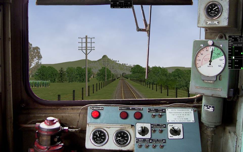
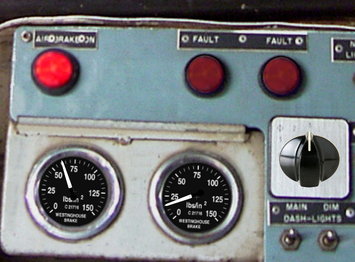
Shown above are two pictures of one hi-res 2D cabview, one showing the whole cab, and the other one showing the detail of some controls. In this example the cab background image used was cut down to 2560x1600. The texture for the Speed Recorder needle is 183x39 and for the brake gauge needles is 181x29, Note the odd number for the width. This is required as OR (and MSTS) assume the needle is in the center of the image. The Reversing and Headlight switch animation frames are 116x116.
There are as yet no specific tools to create these cabviews; a standard image manipulation program to do all textures is required, and to create any new items, e.g. the gauge faces, a standard drawing program can be used. To actual set up the cabview and to position the animations the .cvf file is modified with a standard text editor, and OR is used as a viewer, using a straight section of track on a quick loading route. Through successive iterations one arrives quite quickly at a satisfactory result.
14.1.6. Configurable Fonts
OR supports a configurable font family, with font size selection, and a choice of regular or bold style. More than one font or size can be used in the same cabview. This does not affect the display in MSTS.
An optional line of the form ORTSfont ( fontsize fontstyle "fontfamily" )
must be inserted into the .cvf block of the digital control or digital clock,
where fontsize is a float (default value 10), fontstyle an integer having
the value 0 (default) for regular and 1 for bold, and fontfamily is a
string with the font family name (ex. “Times New Roman”). The default is
“Courier New”. A convenient font, if available, is “Quartz MS” or “Quartz”,
which models a 7-segment display.
Here is an example that displays the digital clock with a 12 pt. bold font using the Sans Serif font family:
DigitalClock (
    Type ( CLOCK DIGITAL_CLOCK )
    Position ( 40 350 56 11 )
    Style ( 12HOUR )
    Accuracy ( 1 )
    ControlColour ( 255 255 255 )
    ORTSFont ( 12 1 "Sans Serif" )
)
It is acceptable if only the first parameter of ORTSFont is present, or only the first two, or all three. Note that you cannot use the MS Cabview editor on the .cvf file after having inserted these optional lines, because the editor will delete these added lines when the file is saved.
14.2. 3D cabs
The key to enter into a 3D cab (if the player locomotive has one) is
<Alt+1>, in case locomotive has both 2D and 3D cabs provided.
Key <1> can also be used to enter to 3D-cab-only locomotives.
14.2.1. Development Rules
The 3D cab is described by an .s file, the associated .ace or .dds files, and a .cvf file having the same name as the .s file. All these files reside in a folder named
CABVIEW3Dcreated within the main folder of the locomotive.If the .cvf file cannot be found in the
CABVIEW3Dfolder, the 3D cab is associated with the .cvf file of the 2D cab.Instruments are named with the same conventions as 2D cabs, i.e.
FRONT_HLIGHT,SPEEDOMETER, etc.A cab can have multiple instances of the same instruments, for example multiple clocks or speedometers.
Instruments are sorted based on the order of their appearance in the .cvf file, for example
SPEEDOMETER:0corresponds to the first speedometer in the .cvf file,SPEEDOMETER:1corresponds to the second one.An instrument can have multiple subgroups to make the animation realistic, for example,
TRAIN_BRAKE:0:0andTRAIN_BRAKE:0:1belong to the instrumentTRAIN_BRAKE:0. However, if the instrument is a digital device, the second number will be used to indicate the font size used, for exampleSPEEDOMETER:1:14means the second speedometer (which is digital as defined in .cvf) will be rendered with 14pt font. This may be changed in future OR releases. The important information for a digital device is its location, thus it can be defined as an object with a small single face in the 3D model.Animation ranges must be in agreement with the .cvf file
Within the Wagon section of the .eng file a block like the following one has to be generated:
ORTS3DCab(
    ORTS3DCabFile ( Cab.s )
    ORTS3DCabHeadPos ( -0.9 2.4 5.2 )
    RotationLimit ( 40 60 0 )
    StartDirection ( 12 0 0 )
)
It is also possible to animate the wipers, by inserting into the .s file an animation named
EXTERNALWIPERS:0:0Gauges of solid type have to be named
AMMETER:1:10:100; where the three numbers indicate that this is the second ammeter, that it has a width 10 mm, and a maximum length of 100 mm. The color and direction/orientation follow those defined in .cvf files.Digits for 3D cabs can now use custom ACE files; e.g. name the part as
CLOCK:1:15:CLOCKS. This will draw the second clock with 15mm font dimension, with theCLOCKS.ACEfile inCABVIEW3Dcontaining the font. If no ace is specified, the default will be used.Mirrors and doors can be operated from 3D cabs. The names used are
LEFTDOOR,RIGHTDOORandMIRRORS.like the 2D cabs, also 3D cabs can have a night version. Night textures, named like the corresponding day textures, must be located within a
NIGHTsubfolder of theCABVIEW3Dfolder. To enable night cabs an.sdfile with the same name as the shape file of the 3D cab must be present in theCABVIEW3Dfolder. This.sdfile has a standard format and must contain following line:ESD_Alternative_Texture ( 256 )
How to control the view in a 3D cab is described here.
A demo trainset with a 3Dcab, that may be useful for developers, can be downloaded from: http://www.tsimserver.com/Download/Df11G3DCab.zip.
14.2.2. A Practical Development Example For a Digital Speedometer
Let’s suppose you wish to create a digital speedometer using a size 14 font.
To explain it in gmax language, you must have an object called SPEEDOMETER
in the cab view and it must be comprised of at least one face.
As the sample cab has only one digital speedometer, it can be named
SPEEDOMETER_0_14.
The number 0 indicates that this is the first speedometer gauge in the cab and the number 14 indicates the size of the font to display. Note that an underscore is used to separate the numbers as the LOD export tool does not support the use of colons in object names when exporting. More on this later.
The speed does not display where the face for the SPEEDOMETER object is
located but where the pivot point for the SPEEDOMETER object is located.
Normally you would place the SPEEDOMETER object somewhere in the cab where
it will not be seen.
With the SPEEDOMETER_0_14 object selected in gmax, go to the Hierarchy
tab, select Affect Pivot Only and click Align to World to reset the
orientation to world coordinates. Then use the Select and Move tool to move
the pivot to where in the cab you wish the numerals to appear. As you have
aligned the pivot point to World coordinates the numerals will display
vertically. As most locomotive primary displays are normally angled you may
have to rotate the pivot point so that it aligns with the angle of the
display screen.
Export the .S file for the cab as usually.
You will then have to uncompress the .s file for the cab using Shape File Manager or the .S file decompression tool of your choice.
Then open the .S file with a text editor and search for the letters “speed”
until you find the first instance of SPEEDOMETER_0_14 and change it to be
SPEEDOMETER:0:14. Search again and find the second instance of
SPEEDOMETER_0_14 and change that also to SPEEDOMETER:0:14. Save the
.S file in the text editor.
Now just one more thing. Download the DF11G3DCab demo trainset. In the
CABVIEW3D folder of that download you will find an ace file called
SPEED.ACE. Copy that file and paste it into the CABVIEW3D folder
for your model.
Now, open OR and test your speedometer.
14.2.3. FUEL_GAUGE for steam locomotives
The FUEL_GAUGE dial is available also for steam locomotives. It may be used both to display a fuel level for oil burning steam locomotives (also in 2D cabs), and to animate the coal level in a tank loco. Default unit of measure is Kg; alternate unit of measure may be LBS. Here below an example of an entry for a 3D cab:
Dial (
Type ( FUEL_GAUGE DIAL )
Style ( POINTER )
ScaleRange ( 0 5000 )
Units ( LBS )
)